Greetings!
Welcome to Scifi-Meshes.com! Click one of these buttons to join in on the fun.
Quick Links
3DFreak's Trek Build's

 1088
Posts: 4,361Member
1088
Posts: 4,361Member


**Edited to update Thumbnail**
**Edited to update Thumbnail**
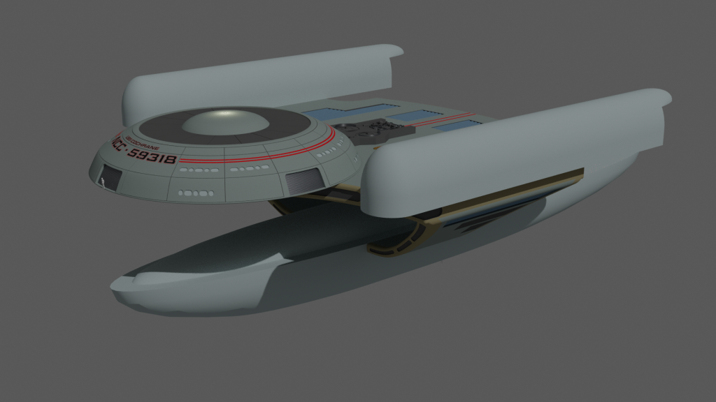
With having built the Enterprise for Star Trek TOS and the shuttle. I still got that modelling itch that needs to be scratched, so I have decide while I have it why build each version of the Enterprise from Star Trek. However for the Enterprise A I won’t do another Refit Connie, I’ll just redo the Textures and the Reg.
Each Ship will be to scale.
With that said, onto the next Build and I am starting of with the Refitted Enterprise.
I am using the plans by Monte R. Johnjulio Enterprise. These are not to bad, though I have found while getting the impulse engines to match from a top and side view, when on a rear it out quite a bit, after resizing the picture to get it to fit it will knock something else out. So unless someone knows of better plans these will have to do
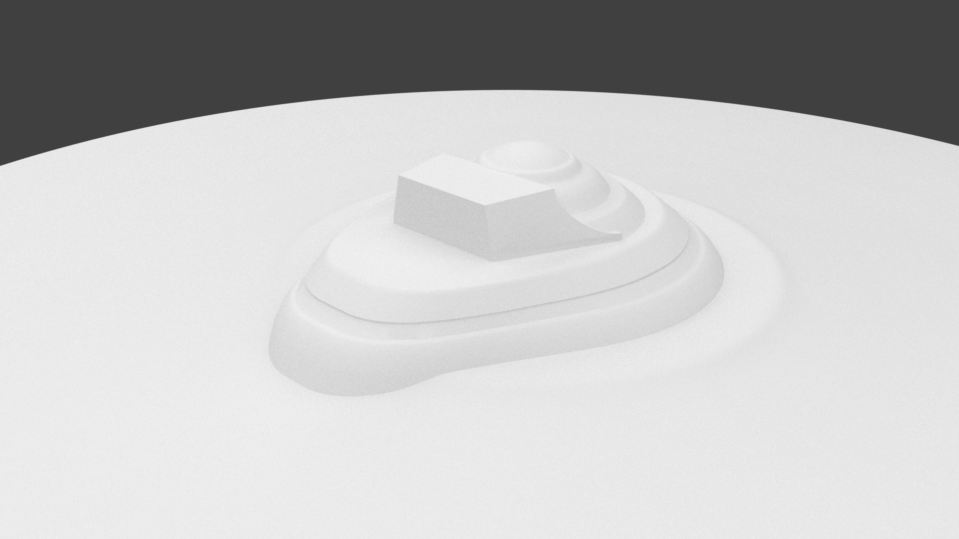
I made the saucer the B/C Deck and the roughed out the bridge.
I lost count how many times it took to get it to were it is now. I am happy with the front end it the rear I am not happy with. I can’t seem to get the shape right, but I will keep at it.
With that said, I am extremally happy with the way the B/C deck turn out, I just need to sort out the area for the large windows at the back.
**Edited to update Thumbnail**
With having built the Enterprise for Star Trek TOS and the shuttle. I still got that modelling itch that needs to be scratched, so I have decide while I have it why build each version of the Enterprise from Star Trek. However for the Enterprise A I won’t do another Refit Connie, I’ll just redo the Textures and the Reg.
Each Ship will be to scale.
With that said, onto the next Build and I am starting of with the Refitted Enterprise.
I am using the plans by Monte R. Johnjulio Enterprise. These are not to bad, though I have found while getting the impulse engines to match from a top and side view, when on a rear it out quite a bit, after resizing the picture to get it to fit it will knock something else out. So unless someone knows of better plans these will have to do
I made the saucer the B/C Deck and the roughed out the bridge.
I lost count how many times it took to get it to were it is now. I am happy with the front end it the rear I am not happy with. I can’t seem to get the shape right, but I will keep at it.
With that said, I am extremally happy with the way the B/C deck turn out, I just need to sort out the area for the large windows at the back.
Post edited by Freak on


Tagged:
Additional credits
- Icons from Font-Awesome
- Additional icons by Mickael Bonfill
- Banner background from Toptal Subtle Patterns
© Scifi-Meshes.com 2001-2024
Posts
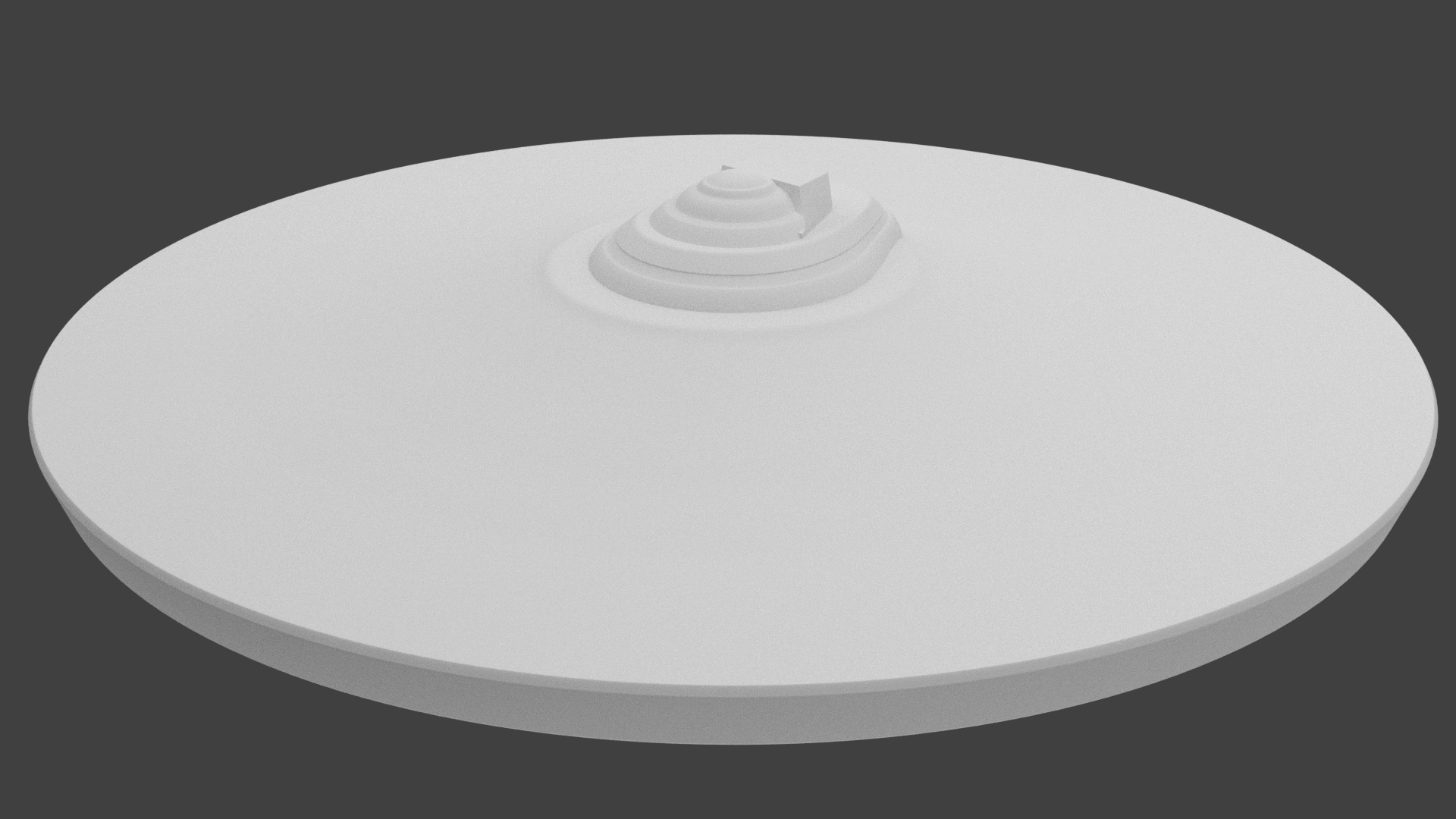
I really not happy with the bridge, so I am redoing it again.
I was just going to rough out the basic shape, but I got into the grove and just went out and detailed it.
I plan to detail the B/C Deck and then get back to roughing out the rest of the ship.
With that said, he is the updated version of the bridge.
That's the best kind of groove to be in! It's kinda zen in a way.
EXAACTLY!!!
I won't be able to work on this, this week. The Wife and I found out last night her BFF is flying in today and will be spending the week. (Wife thought it would be next week.
Not to sure on the lounge windows. They don’t seem to be the right shape, and I have rebuilt them about four times. I think this is the close to what was actually used.
Next I am going to start work on the lower side of the saucer.
Oh and yes, you are correct about the lounge windows not quite being canon. That being said, the ones you put on have a nice shape to them.
All and all an exciting start.
The only issue I see with the lounge windows is that the top edge of the outer two doesn't slope down like that. The bottom edges look good, as they follow that curve. So, if you straighten out that top edge, you'll be right on the money.
@Brandenberg, yeah I know they are a bit on the wide side but I like the look of it (and it was pain to get that close,
Thanks to MadKoiFish, he kindly made his Reference martial on Refit Connie available on 3Dscifi.com
They included the model blueprints by Big Jim Slade. These are much better than the one I had been using to this point and been very helpful with the building of the lower Navigation and sensor dome.
Next I am going to work on the gridlines on the top and bottom of the source and then I can start on the impulse engines.
Let me know if you want me to go more detailed than that though. Happy to help. This is a daunting project to get right. It's a nice start though
Frequent updates at our Discord channel!
The blueprint I was using to start this build are not that great. But thanks to MKF references which included Big Jim Slade model blueprints, they are much easier to follow.
At this point not sure if I am going to go with 100% accurate, I'll see how the build goes.
If I go the 100% accurate I'll have to redo the rear of the bridge as it too wide and the lounge windows.
I going to rebuild the source tomorrow which will resolve the sharpness issues.
Thanks for the advise and if I have any question I'll let you know.
Dang bro, if I'd known Big Jim Slade's blueprints were that good, I'd have clued you into them earlier, when you were asking for plans. I know where to find them, I've just never bothered looking at them before you mentioned them:
https://www.cygnus-x1.net/links/lcars/slade.php
Frequent updates at our Discord channel!
What do you guys think of the grid lines?
Are they too deep or too wide?
The picture was render with Blender internal Render as with my lighting set up in Cycle it did not show up as well.
Excellent work, Dean!
Frequent updates at our Discord channel!
I have now figured out how to correct that issues.
I though it looked a to close to the edge. But I placed it where they are on the plans.
Like you said yesturday. The plans have issues.
I need to rebuild the saucer again, due to the issues I was having with the longitudinal lines. So will correct that placement.
Lost count how many time I have redone it today.
But I am doing only a quarter of it to cut down on the work load and use a mirror modifier for the rest.
Then joined it to the line of verts that make up the hull shape. Deleted the unwanted verts and lines so the cuts are visible.
Spin it out to make the hull. (I was only spinning it 180 degrees and using the mirror modifier to cut down on work.)
Once that was done. I selected the verts that was from the inner cut out to the external cut out and duplicated them to make them a separate Meshes and moved it over to another layer to make the longitudinal cut outs.
The first time I Extruded the verts and rotated them from the centre. (which is why the cut out was closure near the centre and wider at the edge as seen in the picture about.)
Now I extrude the verts to the right by centimetre, then move the external vert to match up with the hull as it curved and apply a mirror modifier.
I then select everything in the meshes and duplicate it and rotate it by 22.5 degrees until I got quarter of the hull done.
The I then go back into the saucer meshes and delete half of it.
Before I used the Booleans tool to add the longitudinal cut outs. But that would cause a lot issues that needed cleaning up.
Last night I did a test of to see how long it would take if I just Joined the longitudinal cut outs to the saucer meshes and delete the faces around them and rebuild them.
I got two longitudinal lines done in 45mins while before it was taking over an hour to do the clean up on each line when I used the Boolean tool.
If you have a better way to do it I am all ears. As Viper pointed out the outer edge cut to close to the end of the hull and needs to be moved back. So it needs to be redone.
I am at work at the moment so I am hoping to get it done when I get home otherwise I'll be doing it tomorrow.
Then select all edges that sit on a panel line and add to vertex group (just to make it easy to select them again later). Now at this point you could do them non-destructively as I have on my Akira, which looks fine until you get to hyper close range. If you want super crisp clean ones you might have to be destructive, so select the vertex group, now bevel those edges to the width required (I seem to recall @Viper saying his were 8cm wide...) and then extrude them down along normals to the required depth. Obviously that method is destructive so you want to make sure you get everything spot on at that point.
But I had finished off before I had seen your post.
I deleted all the faces around the longitudinal cut outs, attached it to the saucer and then selected an edge and just kept hitting F to replace the deleted faces and job done.
Here are the results. I slapped a tmep Material onto it as Scifieric mention it was a little hard to see some of the details.