Greetings!
Welcome to Scifi-Meshes.com! Click one of these buttons to join in on the fun.
Quick Links
3DFTL Shuttle Design
Hi folks, designing this vessel for a client who wishes the project to stay under wraps for now, but I have convinced him to allow me to throw some WIP images of the ship up here on Sci-Fi-Meshes as long as I don't disclose details of the project. My argument was that these board's community is a good and valuable resource for feedback, and often you lot might see something I haven't due to being too close to the project, or that you might have useful suggestions that could be worth taking on board. So check this lot out and let me know what you think of the work so far. And yes, this project is the reason why work has stalled on my Corellian Courier model, though I hope to get back to that shortly when I need a little break from working on this at some point.
So for a little context, there will be a larger ship that I'll also be designing which this will serve as a support ship for. The FTL drive system on this ship (the ring assembly to the rear) will be replicated on a larger scale on the larger vessel. These will be futuristic Earth origin ships.
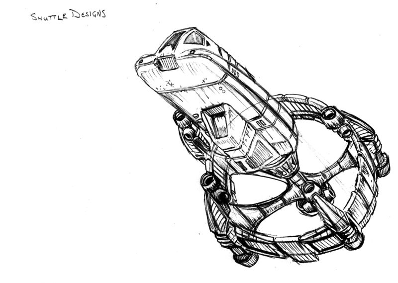
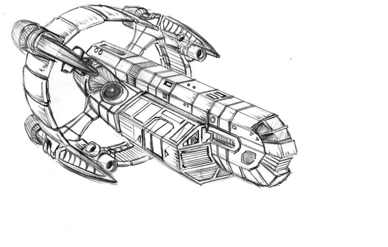
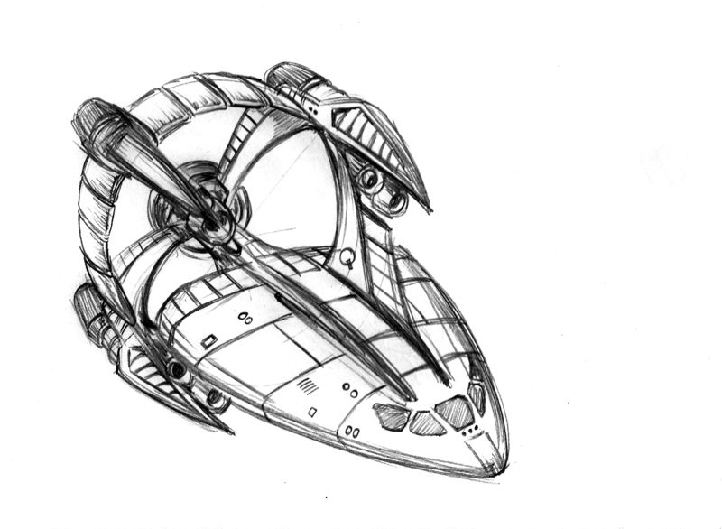
First up, some concept sketches:
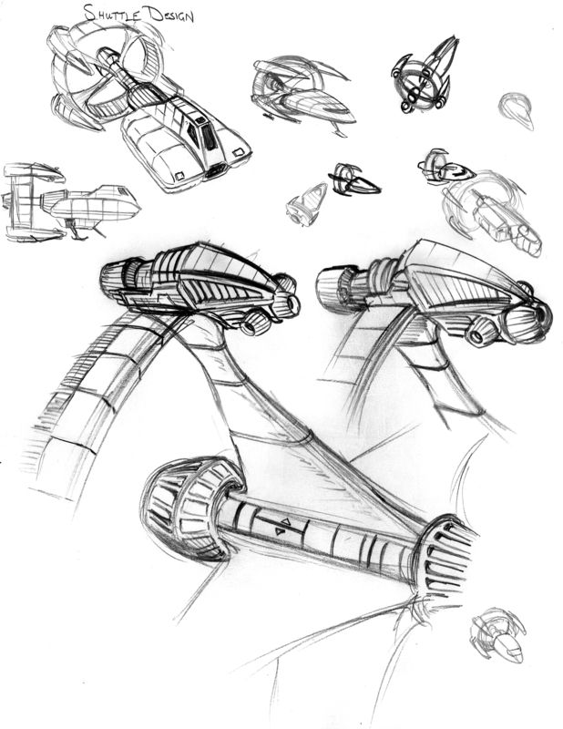
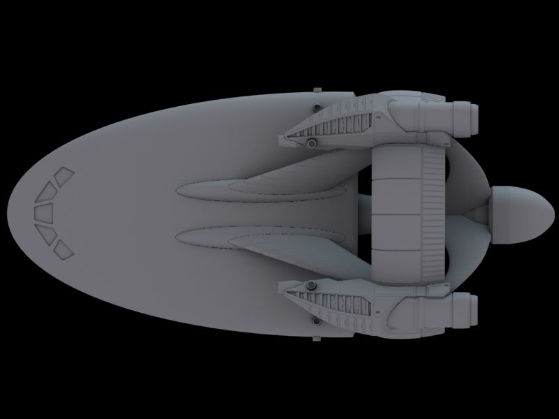
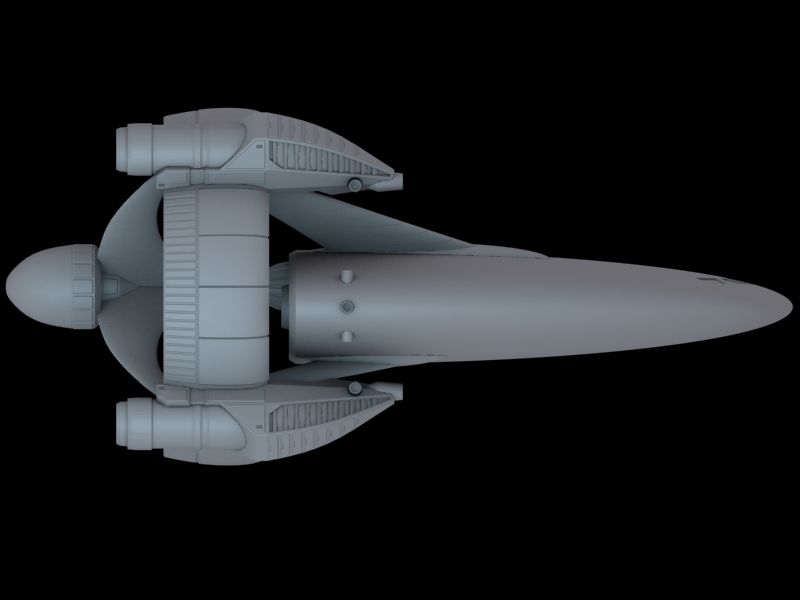
With the client going with the 3rd concept, I blocked this out roughly in 3D to get a feel for all the elements relative to each other in 3D space to see what from the 2D concept worked, and what didn't survive the translation from 2 to 3D:
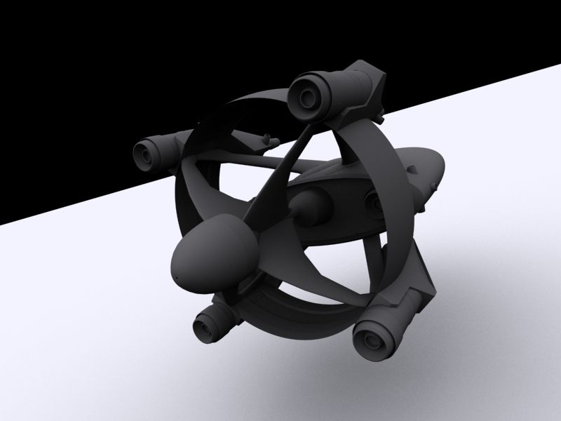
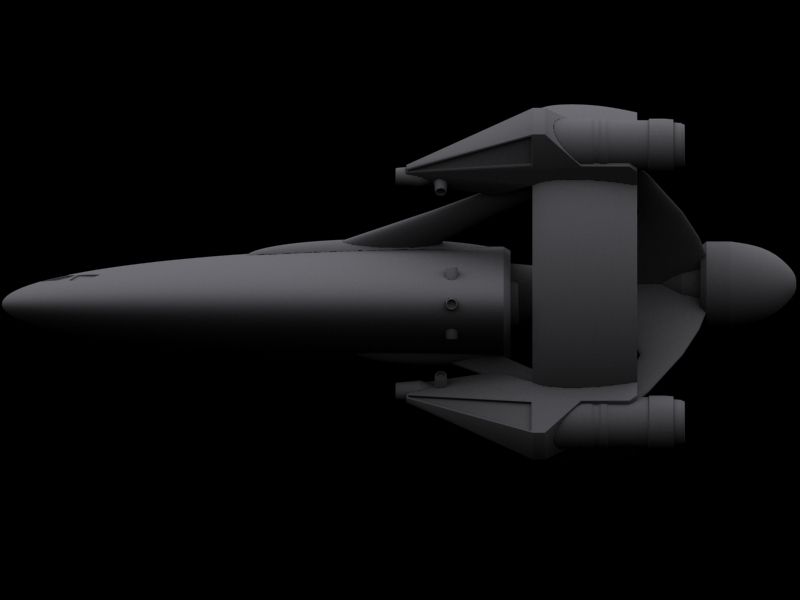
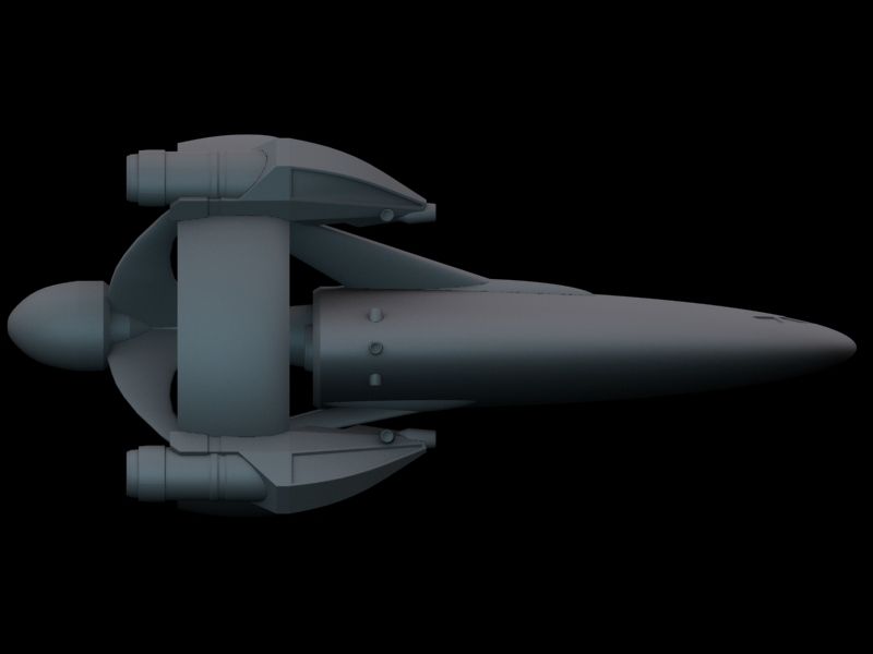
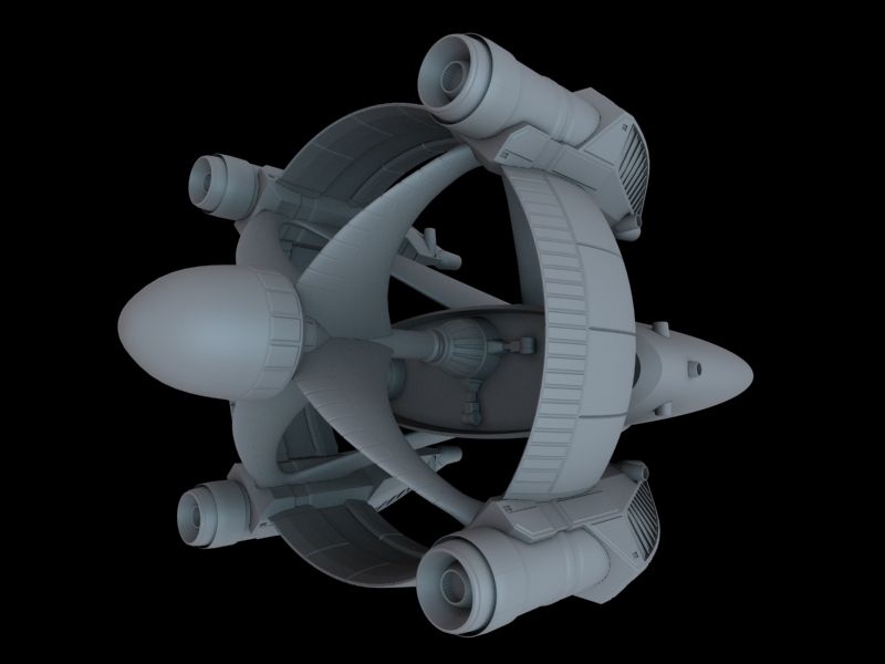
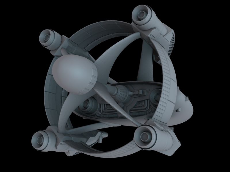
Then came the refinement stage. Working aft forward I started to detail up the shapes of the drive pods on the FTL drive array, it features ion engines for sublight and an FTL drive system effect which is generated by the ring and then dispersed by field emitters towards the front of the pods, there are also manouvering thruster clusters just beneath the nose of each pod. There is also a central mounting rod that the drive pylons attach to at the rear. The bulbs at either end of the rod hold the containment tanks for the matter and anti-matter which fuels the FTL drive.
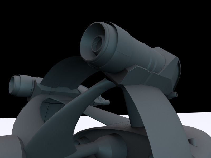
Next up was further finer detailing of the drive pods, and then panel work on the ring and pylons:
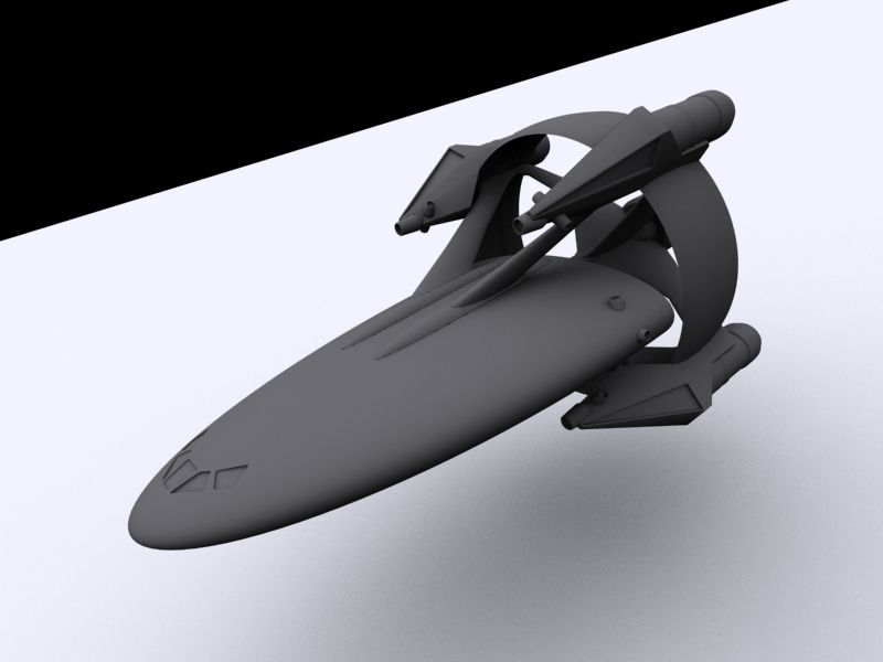
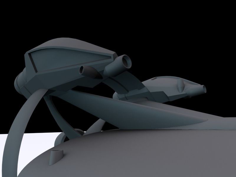
Then looking into the last details on the drive assembly for this detail pass, I refined the look of the central rod that the pylons were mounted on, and looking at the forward containment bulb setting up the first elements on a detachment mechanism so the entire FTL drive section could be jettisoned in an emergency. And of course with the sublight engines also mounted on the FTL drive ring, this led to the need for additional auxilary sublight engines to be mounted on the fuselage of the shuttle too, so should the drive ring be jettisoned the shuttle is still able to navigate at at least low sublight speeds without it.
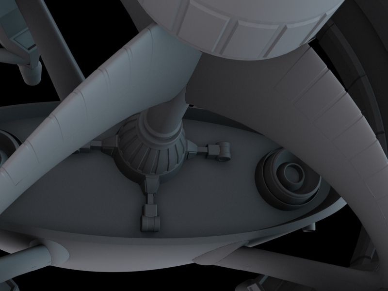
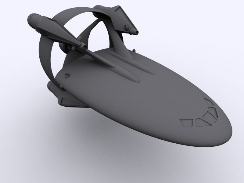
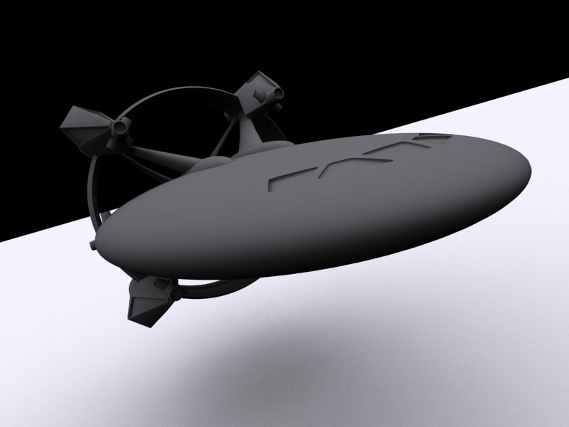
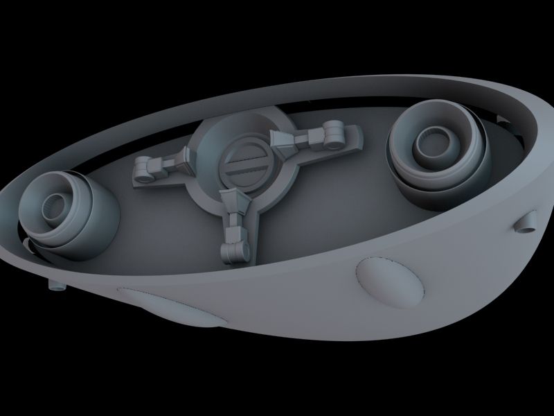
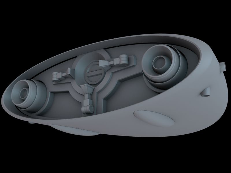
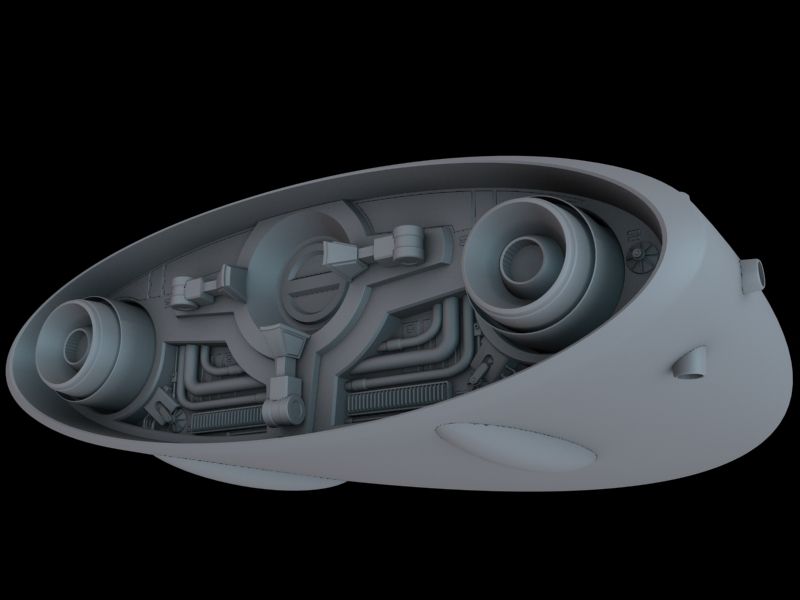
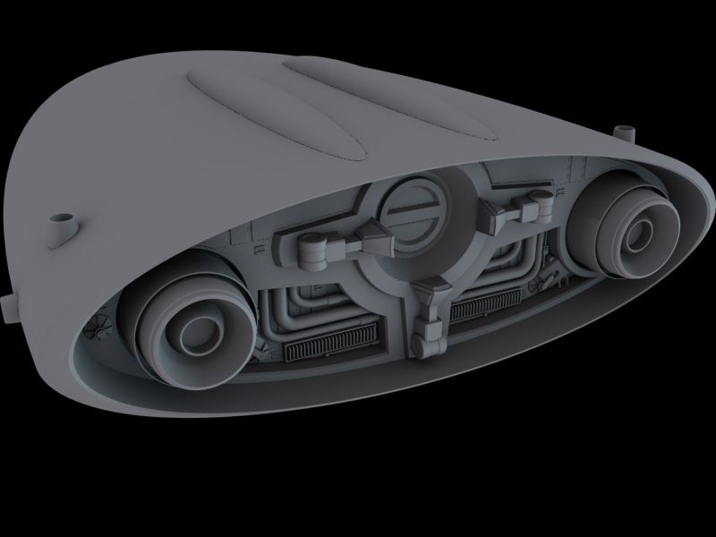
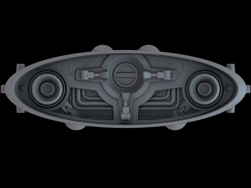
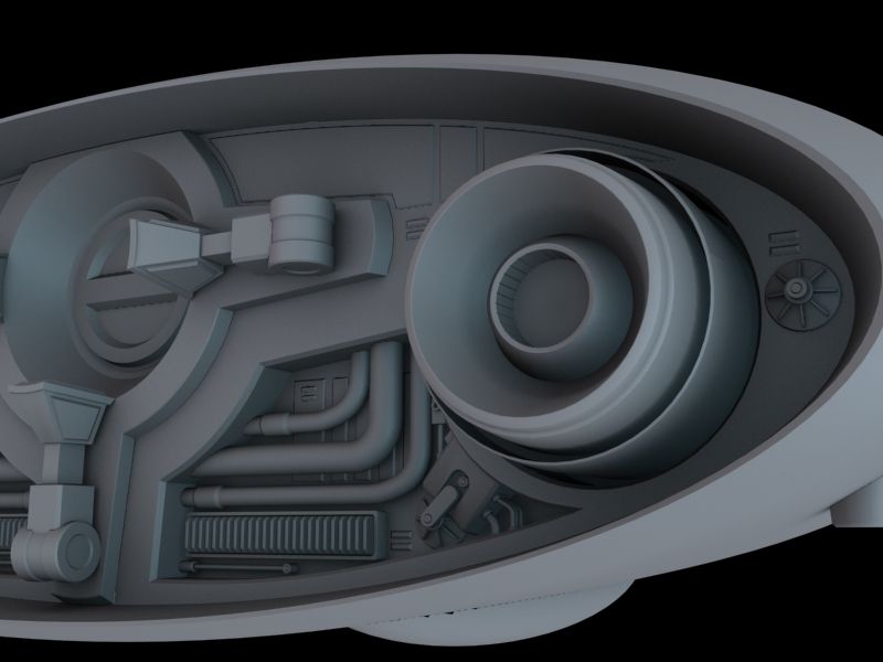
Finally we can leave the FTL drive section behind and move on to the shuttle's main fuselage. Here still starting aft we can naturally progress into this part of the ship through the socket that the drive section's central rod plugs into, and here we can get our greeble on as we detail up the alcove at the rear of the shuttle's body.
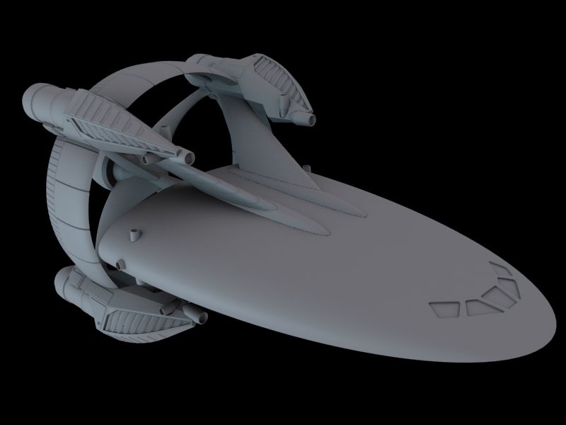
And finally just one shot with the drive assembly back in place so we can see everything that has been done so far together in context.
So a bit of work done on this, but still a bit to go with the detailing up of the hull of the main body of this vessel.
So please let me know what you think of what we have so far. All feedback welcome.

So for a little context, there will be a larger ship that I'll also be designing which this will serve as a support ship for. The FTL drive system on this ship (the ring assembly to the rear) will be replicated on a larger scale on the larger vessel. These will be futuristic Earth origin ships.
First up, some concept sketches:
With the client going with the 3rd concept, I blocked this out roughly in 3D to get a feel for all the elements relative to each other in 3D space to see what from the 2D concept worked, and what didn't survive the translation from 2 to 3D:
Then came the refinement stage. Working aft forward I started to detail up the shapes of the drive pods on the FTL drive array, it features ion engines for sublight and an FTL drive system effect which is generated by the ring and then dispersed by field emitters towards the front of the pods, there are also manouvering thruster clusters just beneath the nose of each pod. There is also a central mounting rod that the drive pylons attach to at the rear. The bulbs at either end of the rod hold the containment tanks for the matter and anti-matter which fuels the FTL drive.
Next up was further finer detailing of the drive pods, and then panel work on the ring and pylons:
Then looking into the last details on the drive assembly for this detail pass, I refined the look of the central rod that the pylons were mounted on, and looking at the forward containment bulb setting up the first elements on a detachment mechanism so the entire FTL drive section could be jettisoned in an emergency. And of course with the sublight engines also mounted on the FTL drive ring, this led to the need for additional auxilary sublight engines to be mounted on the fuselage of the shuttle too, so should the drive ring be jettisoned the shuttle is still able to navigate at at least low sublight speeds without it.
Finally we can leave the FTL drive section behind and move on to the shuttle's main fuselage. Here still starting aft we can naturally progress into this part of the ship through the socket that the drive section's central rod plugs into, and here we can get our greeble on as we detail up the alcove at the rear of the shuttle's body.
And finally just one shot with the drive assembly back in place so we can see everything that has been done so far together in context.
So a bit of work done on this, but still a bit to go with the detailing up of the hull of the main body of this vessel.
So please let me know what you think of what we have so far. All feedback welcome.
Post edited by TALON_UK on
Tagged:
Additional credits
- Icons from Font-Awesome
- Additional icons by Mickael Bonfill
- Banner background from Toptal Subtle Patterns
© Scifi-Meshes.com 2001-2024
Posts
Gigabyte RTX 3080 Gaming OC 12GB
1TB NVMe SSD, 2 x 1GB SATA SSD, 4TB external HDD
32 GB RAM
Windows 11 Pro
Yeah, there are definitely some influences of that nature in there. I was definitely after a design that offered up some nod to Newtonian physics, so a Babylon 5 Starfury instantly comes to mind when you start down that path. so in space at sublight speed this ship uses some form of advanced rocket/ion drive (the client has some specific ideas on the sort of drive it uses), with manouvering thruster clusters for control and navigation in space. The Vulcan influence was an unfortunate one. I decided I liked the idea of having a ring based FTL drive system, but of course as soon as you do that you enter Star Trek: Enterprise era Vulcan ship design territory, and it was my aim to try and distance myself from that as much as I could by making the main body of the ship as utilitarian looking in design and un-Vulcan like by attempting to avoid those elegant lines as much as I could. This wasn't the way it ended up going however, with the main body taking some influence from that second generation delta shaped space shuttle design that was floating around some years ago (which turned up in the opening credits for Enterprise thinking about it), and then elegant lines were somewhat on the table again. The ship is designed to be able to enter atmo, so that is part of the reason for that design decision.
Aye, the center of gravity is a little off. I shifted the main body down a little to make the landing gear situation with the ring attached a bit more manageable. The ring is detachable, but I don't see this as a regularly occurring during normal operations type of affair, more of an emergency measure similar to Star Trek when they dump the warp core. The shuttle's main body will feature a large nose gear for use with the ring attached, but the shuttle will also have a set of shorter gear for the vessel to use should it find itself detached from the ring. This could also be useful for storage purposes, when the ship is stashed away in some deep storage hangar aboard a larger vessel the drive sections could be stored elsewhere and then the ship assembled when needed on the main hangar deck. Also there might be a possibility of the FTL drive assembly being a universal attachment to ships of a certain size and configuration, so the ring might be attached to a cargo freighter or tanker in need of FTL capabilities too.
Yeah, the hatch situation is going to be interesting due to the shape of the shuttle's main body. I'm currently looking at having a section of ventral hull plating split and slide appart to reveal a hatch and boarding ramp within on one side of the ship for use when landed in a hangar or having landed planetside, and then on the opposite side I have an idea for a dorsal and ventral hull plate opening up like a clam shell and revealing within a docking collar and telescoping transit bridge which can extend and attach to a capital ship airlock. Might be a bit complicated, but I think I can make it work. I'd probably also put a topside manually operated hatch in there too which could be used for emergencies, or attach to alternative docking collars from other vessels or something, will have to see how those details develop, and what the client likes the look of.
With the wing situation for atmospheric flight, it is an idea, but with the ring still attached you have something approaching air control surfaces with the pylons, but I think we're going to go with something like Star Wars style repulsorlift like tech to provide lift for atmospheric flight, with perhaps the manouvering thrusters still being used for control and main engines for propulsion. Those heat sinks in the lower half of the greeble pit at the rear of the shuttle body I see being part of the cooling system for this anti-grav tech for atmo flight.
Hope to have more for you soon. The main body detailing should help cement this design as having its own character, and not be too much of an amalgamation of other designs, even if the influences will inevitably still be there to some extent.
Might find a way to incorporate them is some way in the future, either as other types of ship in the fleet, or perhaps as earlier shuttle designs prior to the one currently featuring in the story as the state of the art spacecraft.
But the idea of NASAs FTL drive could help there. I mean sure they used two rings instead of one, but this can always be blamed of advanced tech.
Yeah, as I mentioned earlier, I tried to veer away from smooth lines and go with a more utilitarian design, but got drawn back into smooth shapes by some of the other influences that had an effect on my design ideas for this ship. Hopefully the detailing on the main body will help to differentiate it from Vulcan designs.
Aye, the NASA FTL drive design is probably a big part of why I decided to go with a ring based drive system, making an assumption that this early theory based design works, and that all future Earth ship FTL drives end up using some version of that same system just advancing the technology as time goes on. So yeah, greater design efficiency may take it from two rings down to one.
I think that even though the shuttle is quite sleek, the capital ship is going to stick with a more utilitarian, blocky and modular design. So that definitely shouldn't end up looking at all Vulcan.
As ever any and all feedback welcome.
@ Stormcloud, yeah I have thought about how the wing pylons detach. The answer is in the above renders, but not absolutely clear. The renders of the separated shuttlecraft module aren't quite how the final thing will appear. Those pylon blisters in the recesses are actually the separation point between shuttle and drive section. I have just included them on their own in those renders because it was that point of separation which was the focus of that work. In the final asset those blisters will be attached to the drive pylons, not the shuttle. So when the two separate the blisters will come away with the drive section leaving the shuttle with the recess or trench in the hull plating that the pylon blisters slide out of. The actual method of attachment would most likely be through some form of mag lock, possibly together with sections which extend and interlock with equivalent parts on the other side of the separation point, similar to how the Enterprise-D separates and attaches the star drive hull to the primary hull.
So any feedback would be appreciated on this. Next I'll be looking at developing the actual landing gear and details for the interiors of these orifices as my next task.
As ever, let me know what you guys think.
I had a thought/suggestion, guaranteed worth what you paid for it or your money back, about the aerodynamics of the lander. (I'm a retired flight engineer, low time private pilot, and airplane mechanic, so I've got a habit of thinking about the aerodynamics of anything that is supposed to fly.) If the upper forward fins stayed attached to the lander when the ring detaches, that would give it a swept-back V-tail which would make the lander much more aerodynamically stable and controllable in atmosphere. I know it would also complicate your system for detaching the drive module, so feel free to ignore my unsolicited suggestion.
Whatever you do with this thing, I want to see how it turns out. Press on with pride, man!
Thanks Bosun for the informed design advice. I was at one point considering whether I'd want air control surfaces on the shuttle body for atmospheric flight, but there were a few factors that turned me away from it. The setting and universe the ship is being designed for is a few hundred years ahead of us, so while aerodynamics have still been factored into the design as evidenced by the sleek shape, I figured that the technology used to power the vessel and provide lift and flight control in atmosphere might have moved on from that to something more modern. Having said that I'm still using RCS for flight control in space. I'm thinking in atmo the ship would use a combination of some futuristic anti-grav/repulsorlift style tech for lift, with control support from the RCS thrusters making the need for tail fins and other air control surfaces obsolete. Another factor in my decision is the actual extent of the use of the separation facility. Even though I'm putting quite a bit of effort into it as part of the design process, it is less of a Star Trek style saucer separation, or Star Wars prequel Jedi Starfighter Hyperdrive Ring style affair where separation might be a common operation in the use of the ship. I see it as more of an emergency separation should the FTL drive suffer from a cataclysmic failure, akin to Star Trek when they eject the warp core. In addition it would be used to break up the ship for easier deep hangar storage when not in use, or facilitate the easy modular attachment of FTL capability to ships of a certain class in the fleet that are designed to interface with that style of FTL drive module. So with that in mind the main body isn't a lander as such, as in general operations it would land with the FTL drive module still attached. I just have systems in place on the main body so that should it be forced to detach from the drive module it still has the capability to operate independently of it, and have appropriate auxiliary landing gear to allow it to land without it.
Will the primary landing gear have legs mounted on the drive section? If not, I don't see a need for auxiliary landing gear. Leaving unneeded components off is a good thing; less weight/mass to haul around = more speed and maneuverability, bigger payload, cheaper to build, fewer moving parts to malfunction, easier to maintain, and easier to operate. Maybe less work for you to design it too, if that's a concern.
I guess my thoughts on the design of this ship is that even though it is set some time in the future that space travel is still considered a dangerous thing, and so as a result, even the back-ups have back-ups, that sort of design mindset. So yes, more weight, but this is for auxiliary safety systems, so as I've mentioned before the drive section can separate should something untoward happen, and the remainder of the ship still operate, but further measures can also be taken such as detaching the rear engineering section so that the cargo/passenger bay and cockpit then essentially become an un-powered lifeboat, or as a further last ditch measure the cockpit section also can separate should the main body section somehow be compromised too. I hope that by taking this design route it gives the suitable impression that space travel is still seriously dangerous even with the wonders of new technology hundreds of years in the future, and that unlike say Star Trek where it kind of makes space travel seem easy and commonplace due to a high reliance on technology to solve every problem. I hope it leaves you feeling that the spacefarers of this universe still have a healthy respect for the dangers of space and that it isn't just a walk in the park.
Cheers once again for the feedback, appreciate it.
Now let's have less typing and more ship designing! Get to it, man! Chop-chop! :thumb: