Greetings!
Welcome to Scifi-Meshes.com! Click one of these buttons to join in on the fun.
Quick Links
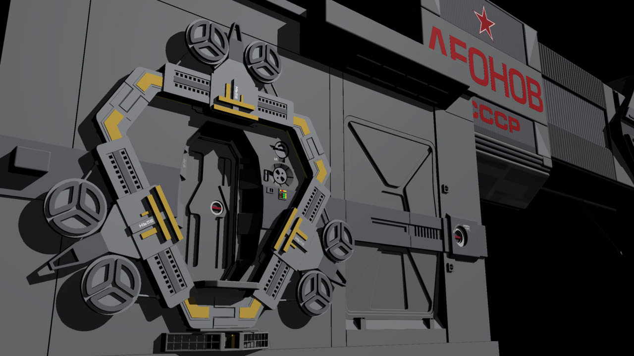
3DSpacecraft Alexei Leonov (Animation:Master, Illustrator)


As I mentioned in this post in Coolhand's thread, this is my take on the Leonov from 2010: The Year We Make Contact that I'm modeling in Animation:Master. I'm drawing a lot of the surface detail in Adobe Illustrator and importing it into A:M with different amounts of extrusion. Most of the repetitive corrugated detail on the ship will be bump mapped.
I began working on this project in May 2009, but I was unable to continue with it for the last several months. Today I'm posting test renders and screenshots up to the point I'm currently at, although I'm not as far along as Coolhand's mesh. I started with the radiators, since they're the simplest to model. The set of six photos from Planet Hollywood Paris that I have (and I don't know if they're the same as the ones Coolhand referred to) provide very useful references.

Building modules along the spine:


In the last render, I lightened the darkest shade of gray used on the hull. I'm planning to redo the cylindrical structure with the dark bands forward of the centrifuge, because after referring to HD screenshots of the movie, I see that it has some rectangular panels attached to the sides.
Post edited by SuddenFrost on
Tagged:
Additional credits
- Icons from Font-Awesome
- Additional icons by Mickael Bonfill
- Banner background from Toptal Subtle Patterns
© Scifi-Meshes.com 2001-2024
Posts
This is the back side of the airlock adapter that connects to the Discovery's airlock, and the corresponding Illustrator drawing. I modeled only one side of the adapter and created three instances of it.
The back of the airlock adapter can be seen very obliquely in one shot of the movie (when the adapter is being jettisoned after the war announcement). There's a preliminary sketch of it by Syd Mead in the book The Official Art of 2010:
I provisionally call this semicircular feature on the starboard side of the mast above the airlocks the EVA radar antenna. In the movie, it's hard to get a good look at the strut on which the transceiver is mounted. Maybe I'll go back and greeble it up a little more later.
Front and back views of the main antenna. The shading and panel lines inside the dish, and the indented part in the center, are created with bump and diffuse maps. The ring-shaped feature behind the pickup is a little smaller than seen in the movie, and I'll have to scale it up. The back side of the antenna is based on this photo of the studio model at Modelers, Miniatures and Magic.
When I started modeling the command module, I initially just wanted to make the interior seen through the bridge windows a plain red box with the silhouettes of two chairs visible through them. Later on, I decided to texture the box with screenshots of Captain Kirbuk and First Officer Svetlanov. It wasn't until after I modeled this that I became aware of the casting of the nose section that was being auctioned off at WorthPoint, so with this new reference available, I'll need to modify the model as noted.
For now, I'm working on the engines in a separate project from the rest of the ship. I've tried to duplicate Mead's drawing as well as I can, although I see his perspective is slightly off. The cowling around the nozzles is temporary geometry which I'll be completely redoing later. In the drawing, the auxiliary thrusters have horizontally-oriented "gates" around the nozzle apertures, but in the only scene where we see the engines in the movie (shown in the inset at right), they're vertical like the main engines. I'm going to rotate the nozzles after I no longer need to use the drawing as a guide.
The front side of the engine unit, with a closeup on the feature I call the "engine manifold", as seen in the Planet Hollywood photos. The core structure that will fill in the deep gaps between the turquoise parts still needs to be added.
In the movie, we can see that in order to apply braking thrust, the auxiliary thrusters swing out sideways, and a section of the hull plate moves to deflect the exhaust forward. This is something I'm interested in implementing on this model, and I'm working out how to handle the rigging.
In the Planet Hollywood photo, the swing arm and the bottom of the cowling that it's attached to are sort of a brass color, which makes me think somebody may have started doing restoration work on those parts without painting them.
Currently, I'm working on the Illustrator file for the detailing on the rest of the mast, and I probably won't have any new renders to show until this is finished.
However, I've also been thinking about how the sets seen in the movie can be broken up to fit into the ship, and I'll talk about that in my next post.
you can get MUCH better references of leonov... might i recommend: http://www.arapress.com/2010aso.php
I think you'll find that will answer many questions you have, as well as an indepth explanation of the module arrangement. Anyway, you're doing real well by the looks of things so far. I'd perhaps stop working on the engines from that drawing, its no doubt a bit different in the model itself. Also I suspect, given the damage to the model that the copper areas you talk about are exposed because the cladding in that area has been lost or torn off accidentally rather than the result of restoration... but i guess thats beside the point; either way i think you can be sure that its not how it looked in the movie.
btw, i have one crit, its a nitpick and it doesn't really matter imho, but as you're obviously a complete freak you'll want to get it dead on.;) as far as i can tell, the docking adaptor is not an equilateral triangle. its proportionally taller it maybe appears to be at first glance... possibly this is an aspect ratio issue i guess or exaggerated by it, but it seems consistent over all my refs. certainly the cutout for the rings in leonovs hull is not equilateral.
additionally, i had to go and look this up just now, though i have no clear images on it, just the movie for reference, i think how you've setup the thrust reverser is in error, the engine "blocks" either side of the mains does not move, its simpler than that... the door swings back about 45 degrees and the 3 outer engine bells are rotated 90 degrees outwards so the thrust is roughly bounced out in front and err, into the centrifuge...
It's got to be an aspect ratio issue with your display -- the cutout is definitely an equilateral triangle:
And if you think about it from a production standpoint, why wouldn't they want to save money by making the adapter out of three identical segments?
I think you're right about this, and I'll see how I can modify the engine to suit. It's really hard to see what's happening in that scene of the movie because everything's in shadow.
So around the time the 2010 movie came out, TSR adapted it into an adventure module for their Star Frontiers RPG. This book can be downloaded at the bottom of this page: http://www.starfrontiers.com/modules/ (While you're there, don't miss the 2001: A Space Odyssey module, just to see how preposterous it is to try turning 2001 into an RPG.) The 2010 module includes a floor plan of the Leonov interior which seems to have been based on the blueprints of the set. However, it has several inconsistencies with the movie:
The kink in the corridor leading to the Medical Bay was probably there to allow the drawing to be printed on the page. Here I've photoshopped the map to make it closer to how the set was actually set up (the bridge was probably a separate set, though):
But of course, the Leonov as seen in the movie is a TARDIS.
The sleeping quarters could fit if they were split in two, and there's still one module left over which I call the laboratory, something no interplanetary science vessel should be without.
After I finish modeling the whole ship, I sometimes wonder if I should also model the inside of the airlock. I'd have to retcon the design so that the hatches are in the ceiling instead of the aft wall.
If its partly an aspect ratio issue i think its to do with the dvd transfers and so on.. something going wrong with the reproduction of the images before it hits my monitor.. its not particularly difficult to create an equilateral triangle eh? so yeah, i've checked it;) possibly the angle of shot compounds the problem.
from a production pov, it actually makes perfect sense that it might be out a bit on all versions... infact it could be very difficult and more expensive to make 3 absolutely identical sections and my feeling is that this wouldnt fit the design of the cutout and concentric rings anyway.
I'd suggest you have a closer look at the truncated areas of the full scale one you posted, i mean its a minor point, like i said its a nitpick... but based on my measurements, its definately not the same on each side, even though the angles between them on this version may be... i think you can ignore the disymmetry along the top as merely a production error, but the longer length on the sides seems to be a design choice. possibly they were building it around that doorway, and it just had to be a bit longer on those sides... so technically, yes you can overlay an equilateral triangle and at least on the full scale it pretty much matches.. but not all the sides are the same length.. try it yourself:)
As for fitting the interior in there, good luck:D Any ideas where they kept the fuel?
Fuel storage? Forget it, it's a riddle for the ages. If you want a design for the Leonov that actually makes sense, there's Tom Peters' model based on Clarke's description in the novel: short, stubby and with no artificial gravity.
On page thirty, Clarke states that there are four huge fuel tanks, that are drop tanks. These serve to get the ship going from Earth.
So as you have asked "where is the fuel?" well there is only one place for it - radiation shielding between the fusion ractor and the habitat section. On the model, this would be the portion of the ship between the engine modual, and axis of rotation, and would function only as additional radiation protection... There would be just enough to move the ship into Jupiter orbit, and to (using a gravitational slingshot approach) get home.
Remember by the time the ship was to come home, the ship's mass would have been reduced considerably. So not much in the way of fuel would be needed.
Bye
A lot of production designers don't understand how centrifuges work, and how you'd have to arrange the decks to accommodate them. (For instance, did you see the Virtuality pilot movie, where the characters were walking on the wrong side of the centrifuge?) Also, trying to film the hub of a centrifuge where people have to transition between the stationary and rotating sections is an expensive undertaking: either you'd have to build an elaborate rotating set, which Kubrick did in 2001, or you'd need lots of greenscreen work and make the set entirely CGI.
I know that in 2010 you couldn't tell the difference between the centrifuge and zero-gee areas of the Leonov based on the way the characters walked, but the same was also true of Discovery's pod bay in 2001. Let's face it, the way the centrifuge was handled in 2010 doesn't make much sense. They only stopped the centrifuge when the Leonov was docked to Discovery, but they kept it spinning even when they were aerobraking and when the ship was under thrust. In any case, pretending to move as if you're in zero-gee is very difficult for actors and directors to conceive of, and most productions don't do it -- some exceptions are Star Cops and The Cape.
And good to see how you solve the deck problem, excelent job!
The next lot after this, #692, is the foam Leonov study model that they tried to sell last year at the same time as the miniatures of the Soviet pod, the probe, Io's surface and the 12' forward half of Discovery, but nobody bought it that time. It does look fairly lame.
Oblagon doesn't cover any of Mead's work in Aliens, only STTMP, Tron, Blade Runner and 2010.