Greetings!
Welcome to Scifi-Meshes.com! Click one of these buttons to join in on the fun.
Quick Links
3DU.S.S. Coronado, Katana Class Starship


 373
Posts: 704Member
373
Posts: 704Member


This one's going to require some backstory.
In 1991, the Star Trek: The Next Generation Technical Manual came out, as a codified version of the show's technical bible intended for public consumption. At the very end of the book, the authors (Rick Sternbach and Michael Okuda) included a set of four drawings for the potential future direction starships might take, ranging from familiar to bizarre. One of those designs has a pretty clear lineage in becoming the Sovereign class (albeit with a widened saucer, rather than the elongated one that Sovereign ended up with). Another of those designs, though, had an interesting arrangement of modular segments comprising its saucer, along with wide warp nacelle pylons meant to allow the warp nacelle position to change mid-flight (an idea that would eventually manifest with Voyager's variable warp nacelles).

An artist you might have heard of, Mark Kingsnorth, made a rough model of this ship in the late 1990s that gained some notoriety. It came to the attention of a fellow named "Jester", who asked for Mark's permission to use images of the model on a Star Trek IRC-based role-playing game website. The name of that game was U.S.S. Coronado...and I was one of the players.

Mark's interpretation didn't quite fit with what Jester wanted out of the ship. Jester called it the Katana-class, a frigate-sized ship centered around two major technologies: the launching of small, one-man fighter craft and the use of quantum slipstream drive (originally featured in the Voyager episode "Hope and Fear"). A neophyte CG artist myself at the time (1999), I offered to take a crack at providing Jester with an "in-house" version of the model that we could use to make any sort of shots he wanted. I knocked together a (by current standards) crude model in trueSpace, and away we went!

Later, in 2003, another player (and close friend of mine) on Coronado would build a new set of 2D orthographic blueprints, riffing on Sternbach's original design and incorporating the various design elements that Jester had always intended for the game, namely the "slipstream" deflector as seen on Dauntless in "Hope and Fear" and catapult-style hangar bays for the ship's Spectre class fighters. Having improved in skill significantly since the first trueSpace model, and now working in LightWave, I used these blueprints to make a new model of the ship.

The game ended in 2004, after 7 full years. Jester chose to end it then, since it mirrored the seven seasons enjoyed by TNG, DS9, and VOY. As a gift to both Jester and a wedding gift for the blueprint maker, I had a 36x24" poster of the ship's ortho renders and a few action shots, accompanied by specifications and signatures from many of the players, printed out for each of them, as well as myself. My copy currently hangs in my living room.
This year marks the 10th anniversary of Coro's last game, which took place at the end of August. For the finale's decennial, I wanted to create a new model that goes back to the sources that first inspired Jester -- Sternbach's original design and Dauntless from "Hope and Fear" -- and more intelligently incorporate design elements that would speak to the Katana class's lineage -- namely, those seen on the Sovereign class.
(Side note: Mark Kingsnorth went on to revisit his original take on Sternbach's design, which has gained quite a bit of notoriety as the Insignia class.)
So far, I have been focusing on locking down a completely new approach to the aft saucer, taking a lot of cues from the Sovereign lines on the dorsal surface and trying to more closely match the Dauntless lines on the ventral surface. I've been doing a lot of quick, rough renders and mock-ups, then painting over them with my Wacom tablet in Photoshop to explore different lines and arrangements. I'm using the player-made blueprints as a starting point for scaling, but not treating them as sacrosanct the way I did for the 2003 model. The following images show the evolution of the model from Jan 9 through to today.
Saucer design exploration, focusing on the flight deck and impulse area

Stardrive design exploration, emphasizing the Dauntless-esque shape.

My goal is to have the model render-complete by the end of August, 2014.
Post edited by McC on
WIP: [ SDF-1 Macross ] Done: [ Coronado | Ambassador (original) | T'Varo ]
Books: [ Ashes of Alour-Tan | Embers of Alour-Tan ] | Blender Tutorials | Blog
Books: [ Ashes of Alour-Tan | Embers of Alour-Tan ] | Blender Tutorials | Blog
Additional credits
- Icons from Font-Awesome
- Additional icons by Mickael Bonfill
- Banner background from Toptal Subtle Patterns
© Scifi-Meshes.com 2001-2024
Posts
On your ship, I definitely like what you're doing so far. Since this is supposed to be a more advanced design, getting away from the more or less Galaxy look of Mark's model makes sense. Though, his would work as an earlier class. For the saucer back, I like the elongated shuttle area and the one with the two round cut-outs, those both have great promise, in my opinion. I think the middle idea with the doodles on it looks good for the secondary hull/saucer connection area. I'm definitely looking forward to seeing what you do with this design.
There's a giant post at the start of this thread that talks all about it.
Books: [ Ashes of Alour-Tan | Embers of Alour-Tan ] | Blender Tutorials | Blog
So, yes, basically.
Books: [ Ashes of Alour-Tan | Embers of Alour-Tan ] | Blender Tutorials | Blog
Nice work here, definitely seeing relations to the Insignia. And nice seeing the progression through the ages.
Indeed it is! The Spectres were basically Trekked up Bearcats. For a long time, the only reference we had for what Spectres were supposed to look like was a painting of a Bearcat. I took a crack at modeling a low-res one, meant to accompany Coronado in her renders, when I did the second version of the ship in 2003. I'll probably do the same thing again for this one, going a little more Trek and a little less "hey, this is straight out of Wing Commander..." this time, too.
For now, I just took one of the old renderings and slapped it on a box for scale reference.
Finished merging the saucer and stardrive into one continuous mesh this evening.
Still have some cleanup work to do before the subsurf is smooth enough, but it was far less of a bear than I expected it to be. I love how hunchbacked the ship ended up looking with the catapult platform drawn way far out into the stardrive. Before, the slope from what used to be the impulse deck was very gradual and kind of boring. Now? Coro is out to give someone a beatdown.
Books: [ Ashes of Alour-Tan | Embers of Alour-Tan ] | Blender Tutorials | Blog
I know the sovereign lines are attractive to a lot of people but remember how your internal layout works. That wedge on the top is an often mimicked style in fan designs and is the most space wasting part of the Sovereign. The wedge on the bottom is flat and thus is fine. But once you curve the hull of that wedge like every fan design does get useless space when you try to shove decks into those areas that suddenly cut-off and also cut off earlier than any other place on the saucer. The result is strips of decks because the wedge terminates the deck too soon. I determined it was better that such areas be storage bays or fighter bays and not quarters or work areas.
This design looks like the Insignia and it only occurs to me now that Insignia class was perhaps meant to be that ship in the TNG Tech Manual. Amazing what he's done with the ship over the years..
Believe me, after the trial that was figuring out the "real" deck and window layout of the Ambassador, remaining cognizant of space usage is foremost on my mind.
I made an infographic to better explain the timeline of this design's development.
Mark's original take on the Nova, my various takes on the Coronado "Katana", and Mark's Insignia all derive from Sternbach's original design, but are otherwise pretty much independent of one another.
A couple of minor updates, most of which are barely-visible tweaks to the geometry and clean-up. The "chin" still needs a lot of massaging, as do other parts of the cage, but I'm not going to worry about it too much until I need to actually freeze it. Cleaning up the cage only to add more detail usually means all that cleanup is for naught!
Books: [ Ashes of Alour-Tan | Embers of Alour-Tan ] | Blender Tutorials | Blog
Seriously, I'm assuming you mean the bottom of the secondary hull, which does resemble a chin. I can see where it's not quite smooth, but I'm sure it soon will be.
Been making steady progress each night, but haven't been posting it because it's incremental and probably boring to most folks. Finally made enough visible progress that it feels worth posting, though!
Books: [ Ashes of Alour-Tan | Embers of Alour-Tan ] | Blender Tutorials | Blog
No It's not boring. How do you light your scenes? Also could you show how you do the striped blue sensor array and warp engine sections?
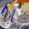
On a side-note, I had always envisioned the nacelles & pylons moving as a unit. The nacelles can shift location along the pylons, but also the pylons could change angle like Voyager's. The upshot of this would be that you could keep the nacelles at the same level (say, just above or below the saucer) and as they shift along the pylons, the pylons would alter angle so that the nacelles spread apart horizontally but maintain their vertical-plane position. I'm probably describing this poorly, the minds eye sees it very well but something gets lost in translation. Mind you, I wouldn't want to do the engineering behind such a system - you'd have to be utterly confident in your warp core and conduit designs - but my inner fanboy thinks it'd look killer.
Currently, the scene is lit from two sources: a white Point light (Size 25m, Strength 6.2^10, using a Math node) at a ~90 degree angle from the camera vector, either above or below the ship depending on where the camera is, and a white Emissive plane (Strength ~0.25) 180 degrees opposite from the Point light, pointing at the ship with a Track To Constraint. I also have Ambient Occlusion turned on, with a factor of about 3% at a distance of 10m. From there, it's all Cycles.
The slipstream deflector and warp nacelles are both riffing on the same basic setup, which is this:
Alas, I have to report that after discussing some of Jester's (see original post) intentions for the ship with him, he never conceived the ship as having externally variable warp nacelles; rather the mechanisms within the nacelles (the warp coils, perhaps) would shift during flight to optimize the warp field, while leaving the nacelle and pylon position static. This excerpt from the old Coro website is the source of the confusion:
The needed breakthrough was finally achieved in 2391, when it was discovered that a ship could safely pass through a slipstream conduit if it possessed both a 45 degree Z-axis compression and a way to neutralize the subspace field stresses of her warp nacelles through the conduit (or eliminate the warp nacelles entirely). The simplest method known to do this was to use variable geometry warp nacelles or struts -- during a slipstream transit, the nacelles could be "stored" in an energy-neutral position.
Now, I read that and see "use variable geometry warp nacelles or struts" -- like Voyager; and "during a slipstream transit, the nacelles could be 'stored' in an energy-neutral position" -- meaning in slipstream, they stay "flat" rather than raised, so he never got a render from me with them raised except for the one very early trueSpace one at the top of the thread -- which he since forgot about.
What he meant was "use variable geometry warp nacelles or struts" -- i.e. either the Voyager approach or an approach wherein the internal nacelle geometry itself reconfigured; the other line thus had nothing to do with external position.
This was news to me after fifteen years and every version of this ship I've made having variable-geometry pylons. :rolleyes: But I suppose that's what I get for never asking him about it until now and never doing a render for him with the pylons raised.
Since Coro isn't exclusively my baby, but rather belongs to everyone involved in the game (and probably Jester most of all), this model won't have any external variable-geometry gear. That's why you see the pylons as a single unit in the most recent renders.
I think it is indeed what Rick originally intended, based on the quick design description from the TNG TM:
Still another advanced starship concept would call for variable-geometry warp nacelle pylons permitting optimization of the field stress during extended Warp 8+ flight, resulting in significantly improved engine efficiencies. This design study features a saucer section composed of wedge-shaped-modular segments that could be easily replaced as mission demands change and new technology becomes available. This concept calls for an internal volume approximately 40% less than the present Galaxy class starship, but this design is expected to perform similar mission profiles within normal cruise ranges because of the relative ease of spacecraft segment swapout.
Based on the image, it looks like the nacelle sits on something like a conveyor belt that slides along the length of the pylon. The pylon itself doesn't exhibit any crease where the variable geometry mechanism (as implemented on Voyager) would sit.
Books: [ Ashes of Alour-Tan | Embers of Alour-Tan ] | Blender Tutorials | Blog
The windows are actually geometry that's been face-snapped onto the saucer and extruded slightly. The windows are all 0.75m across (some crude measurements of Sovereign windows indicated a width somewhere between 1.9 and 3.8 feet, leaning more toward the former). Since the decks are 2.45m from floor to ceiling (Coro is deliberately meant to feel more cramped than most Starfleet ships), I made the windows 1.35m tall, raising 1m off the floor and giving a 10cm clearance between the top arch of the window and the ceiling.
The inner-most windows shown (Deck E) are actually portholes when viewed edge-on; 0.75m circles. It's only the extreme slope of the deck that makes them look so elongated. If you were standing inside the ship facing out one of those windows from where the "top" starts, you'd have 5 meters between you and the bottom of the window, which is awfully huge for a porthole. The Deck F windows (next row out) are the same vertical height as the Deck G (outermost) windows, yet they stick into a room almost as far as the Deck E portholes do. The Deck G windows, for contrast, only stick in about 1.8m -- much more reasonable. So, I may ditch the E and F windows entirely.
The non-module windows have a different arrangement pattern than the modules do. The modules all share the same pattern.
I threw some annotations on the modular components to indicate intended functionality and relationships. The main phaser array interlocks emitters between the modular segments and the module spars, creating a single continuous strip regardless of the ship's mission configuration.
C&C (and suggestions!) welcome.
Books: [ Ashes of Alour-Tan | Embers of Alour-Tan ] | Blender Tutorials | Blog
Nope! Shrink Wrap is a dirty, evil modifier that I try to avoid wherever possible. Face Snapping is one of the many snap modes Blender provides (accessed from the bottom menu in the 3D View, or via Shift Tab) and will snap your current selection onto the nearest face "behind" it, depending on what view you're looking through. It's a little goofy to use, but incredibly useful!
Here's where I left the paintover and decided to come back to modeling:
And here's the current state of the model! The main hull is frozen and optimized here, though the modules, nacelles, and bridge (not pictured) are still unfrozen. I actually frozen the main hull at two detail levels (2 subdivisions and 3 subdivisions), then chopped certain pieces out of the 3-sub mesh and welded it into the 2-sub mesh in order to deal with some segmentation issues. Worked out surprisingly well and isn't a trick I've tried before.
The hull texture on there is just something I slapped together to test for UV distortion (of which some does appear along the center axis, which I'll need to clean up) and probably won't end up as a final texture in any way.
Books: [ Ashes of Alour-Tan | Embers of Alour-Tan ] | Blender Tutorials | Blog
I actually did think about it, but decided against it because it would require me to work in a very specific way, it would be obnoxiously long, and it would mean a lot of extra time doing all sorts of editing to make it presentable and comprehensible. However, making two quick, specific videos on the two techniques you mentioned would be pretty easy to do. I'll try to whip them up at some point in the near future.
Books: [ Ashes of Alour-Tan | Embers of Alour-Tan ] | Blender Tutorials | Blog
Hmm, did you try isolating the trouble parts in the lower subsurf area and using a localized subdivide command on them? Would that work?
Some minor idea-nits:
1) You may want to keep Deck 3 as part of the core hull, rather than part of the segments -- as it is, you don't have much "core" for the modules to dock with, and you'd need sufficient room for your non-modular equipment, such as the main computer core, etc to be kept.
2) Rather than eliminating a habitat module (whch seems a bit wasteful just for the sake of sticking name and reg plaques on!), why not just situate the pennant areas elsewhere, maybe somewhere closer to the core - or even on Deck 3 itself?
3) Not quite sold on the secondary hull; the sides look a bit "tubby" in comparison to the marked arrowhead you've got closer to the front with your deflector array... do you have another angle to see if it's actually the case or just a camera trick?
Looking good!
Seriously, the hull shape looks great.
With the level-2 subsurf, a couple of areas remained too segmented (specifically, areas around the tip of the ventral "delta" and the main deflector), because there just wasn't as much control geometry in those areas to subdivide.
(Click to enlarge)
You can do this, but it often results in some ugly topology in your subsurf due to the weird five-sided polygons it creates. Five-sided polygons in an actual mesh, rather than a subsurf cage, are much more cooperative and don't alter the fundamental curve topology of the mesh itself.
I was thinking about that! Not entirely sure yet. I'm leaning toward having the RCS thrusters on each of the off-axis struts, leaving the axial struts to mount running lights. This would be consistent with how most Federation saucers have their RCS thrusters arranged.
I suspect this is partly an optical illusion, actually, because with the segments in place, it's not clear how they "dock." They actually sit on a huge platform. Here's what the main hull looks like without the module docking collars or modules:
It wouldn't necessarily require elimination of a habitat module; it'd just be one without windows.
It's a bit of both, really. Coro is meant to have a bit of a "hunched" look to her, rather than the sleeker look you usually see in Starfleet ships. She's not there to impress you with her prettiness, she's there to get things done and take no crap in the process. So, she is definitely a bit tubby in some respects.
Here are the front and ventral orthos, for reference all the same:
Thanks!
Hah, thanks! This is the first time I've actually tried this trick. I'm not sure why it never occurred to me to do it before. I suppose mostly because I model things that already "exist" and don't really require a lot of invention on my part.
Fair enough!
Though, fair warning: the "snap to face" trick isn't how I actually make my windows; it was a shortcut to just having some window-like shapes on the hull that I could put on a paintover to think through window layouts. My actual windows are just extruded polygons that are booleaned out of the main geometry and then inset to give them a nice edge.
That method is detailed here. The tutorial's complete, though it's still missing some screenshots for some of the process.
Bwahaha, yeah, it's pretty terrible.
Thanks!
Books: [ Ashes of Alour-Tan | Embers of Alour-Tan ] | Blender Tutorials | Blog