Greetings!
Welcome to Scifi-Meshes.com! Click one of these buttons to join in on the fun.
Quick Links
Local TutorialWings 3d Tuts


Hello, I have noticed that there really aren't alot of tuts for Wings3d on SFM so i figured that some of us Wingers could get together and post some.
Here is one that i just did in response to a Question from a friend in his wip thread...How to Round out the edge of a cude...this is just one way and im hoping more will be shone as well...:) this is Part one:
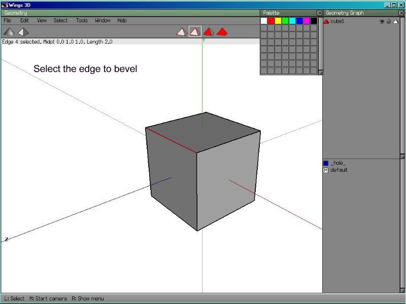

Here is one that i just did in response to a Question from a friend in his wip thread...How to Round out the edge of a cude...this is just one way and im hoping more will be shone as well...:) this is Part one:
Post edited by Lee80 on
Additional credits
- Icons from Font-Awesome
- Additional icons by Mickael Bonfill
- Banner background from Toptal Subtle Patterns
© Scifi-Meshes.com 2001-2024
Posts
I hope some one finds this usefull..:)
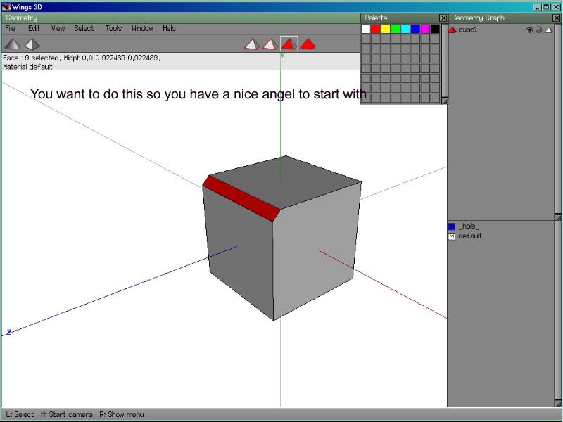
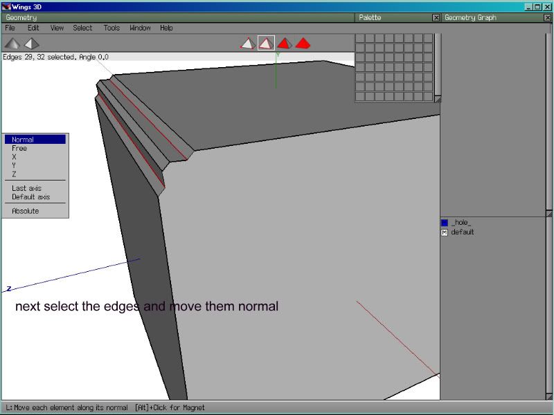
Step 1, bevel the edge.
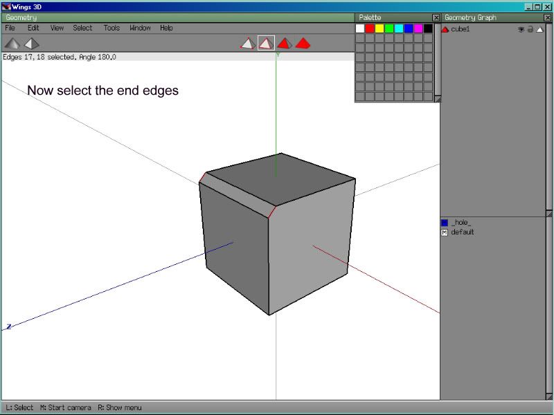
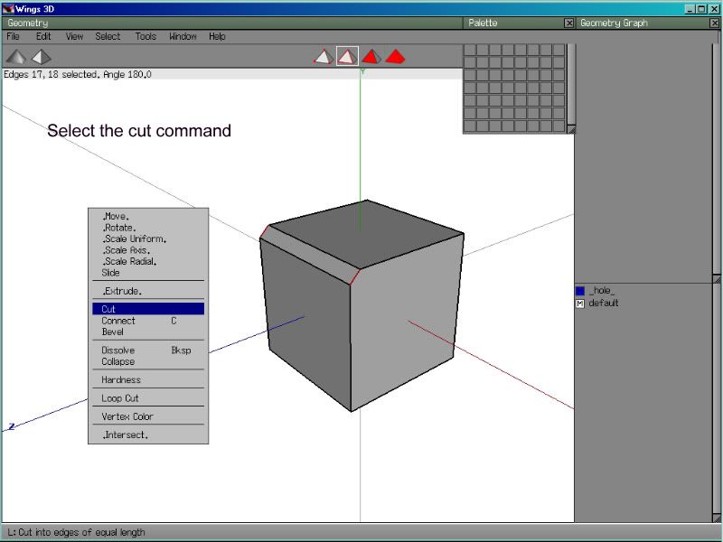
Step 2, bevel the 2 new edges.
Step 3, bevel the 2 new outermost edges.
Step 4, if needed bevel again.
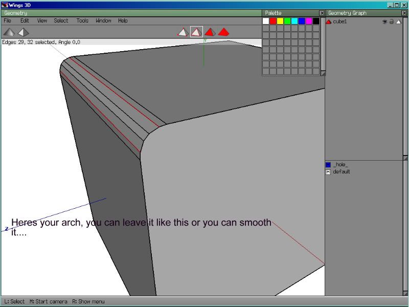
You can vary the curvature by increasing the amount you bevel each time. Here is what you should be left with:
Here's my contribution: Howto panel rounded surfaces without getting ugly mesh errors
I didn't add screens with dropdown menus. if i mentioned/used a command you're not familiar with just ask (or even better search for it, you might find a few other useful things on the way :devil:)
Hope this helps :thumb:
Regards Roman
fixed :thumb:
1)Doin Round Stuff...
2)How to Texture... (wish I had this when I started.)
Hope this helps :thumb:
Regards Roman
How do I prevent this without changing the hardness? When I make it hard it doesn't look like it's actually part of the ship.
Hmm, not sure on that one. perhaps a view of the wire would reveal a solution.
A thought... Where the edge of the phaser stripe (assuming here
BEvelling the edge does nothing. Making if I make it hard it looks a little odd, but I am willing to leave it like that.
That would depend on your poly layout. Like Ozylot said, wire would help
Could we see a shaded view since you hardend that edge? please....
This will not alter your geometry but it will produce those extra loop lenno was talking about both on the phaser stip and on the hull. The one on the phaser strip can be removed as it is not necessary.
This should help.
Regards Roman
take a look at the attached pic:
1 and 2 show what you currently have, with the normals producing shading artifacts. This is because they are smoothly interpolated (soft normals) over a large polygonal area.
Hardening (3&4) of course will get rid of the shading artifacts, however, as you said the hard edge doesn't look very natural.
The solution (5&6) is to add to additional loop, forming a 3 edge bevel, wish will give correct normal smoothing, and appear as a bevel. Of course in it's current state it doesn't look exactly nice, but this is because the phaserstrip is somwhat lowpoly.
I am not sure whether this mesh is meant to be subdivided, if it is, the correct beveled edge (or better–correctly looped edge) will give better results (7) as opposed to the way to organic shape your original layout would produce (8). Vary the edge distance to control the bevel size for both subd and not-subd.
/
I wouldn't suggest an extrusion by zero as this will produce VERY hard to clean up areas. In fact you'll have double edges, hard to spot if you need to do any modifiaction on the part and a pain in the ass really. In some apps this will even produce doubled polygons in certain areas so your better of adding a loop using a loop cut (which works in this case) or manually.
I was faster nevertheless
It demonstrates the use of the bend command. Makes pipe work very simple.
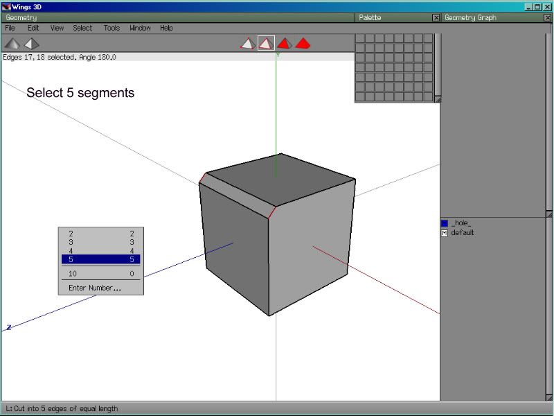
STEP #1:
To start you will need a set up like this.
created by selecting the edges, cutting into 5 segments and connecting the loose verts.
STEP #2:
The first thing the bend procedure requires is the rod center, seems to work well when you pick a point on the side of the bend.
once selected, right click to advance to the next step.
STEP #3:
Next, select a point at the top end of the pipe, make sure its on the same edge as the first point was.
once selected, right click to advance to the next step.
STEP #4:
This can be done a number of ways from here, you can select a face, edge or vertex to do this. In this example ive used a vertex to set the bend direction. a small arrow will appear to indicate the direction.
once selected, right click to advance to the next step.
STEP #5:
At this point the pipe will be able to be bent freely as you move the mouse. Keeping an eye on the number in the top left of the screen will allow you to bend the pipe to precision degree amounts.
Hope this helps, so you don't get all bent out of shape in making pipes. ;D
Yes, you need to activate the advanced menus in the properties to use it.
This one demonstrates the use of several of the advanced commands which are accessed by right clicking on regular commands. Probably the most useful of these is the advanced flatten command.
so lets begin:
We are starting off with an irregular shape, could be an aircraft intake or something, but it will be an interesting vent when were done.
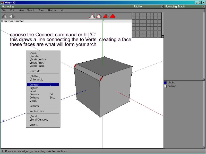
1) Switch to edge mode by clicking on the appropriate icon at the top of the screen or by pressing 'e'. We are going to cut the edges into 10 sections using the cut command. (this can also be done by pressing '0') You will automatically be switched to vertex mode, with the new verts selected.
2)We are now going to create new edges between these verts by using the connect command (can also be done by pressing 'c')
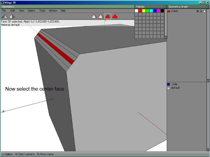
3)Now switch to face mode by using the icon at the top or by pressing 'f'.
next we select the new faces that have been created. There should be 10 of them. We now inset the selected faces by about 70%.
4)At this point we are now ready to use the advanced extrude command. Right click on extrude. (it is important to pay close attention to the info bar at the bottom of the geometry window when using the advanced commands. The text there will guide you through the process)
5)The first thing that the advanced extrude command asks for is a direction to extrude along. as you can see here I have selected an edge for this. A small blue arrow indicates the chosen direction.
6)After extruding the new parts beyond the outer face, we are now ready to use the advanced flatten command. For this procedure you need to hold down Ctrl while right clicking on the flatten command.
7)The first requirement of the advanced flatten command is a direction or normal. As you can see here I have selected the lower face of the object, however in some situations it could have been better to select one of the extruded edges. Right click to accept this selection.
8 )Next thing the advanced flatten asks for is a reference point for the selected faces to be flattened to. Again I have selected the lower face on the object.
Right click to accept this selection.
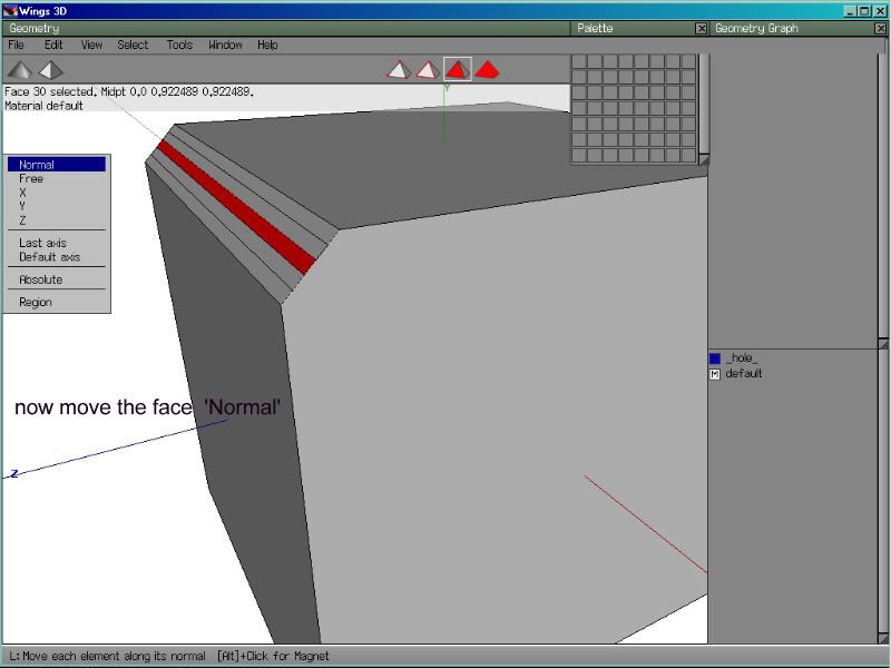
9)Had I used a different reference point on that last step I could have avoided this, the slight amount of overhang from the extrusions can be corrected by a simple Move>Normal
10) and this is what we are left with. I hope you have learned something useful
Nifty. It looks to be better than the simple way I use.
Puzzled Paul's Tutorials
cheers!
Jeff