Greetings!
Welcome to Scifi-Meshes.com! Click one of these buttons to join in on the fun.
Quick Links
3DFinally getting around to Blender (aircraft)
 psCargile417
Posts: 620Member
psCargile417
Posts: 620Member


Figured it was about time for my year end post.
I've been playing around in Blender for most of the year--working on a scene with a model I made in Rhino, and a MakeHuman character that's not ready for presentation yet--reviewing a lot of YouTube tutorials and learning quite a bit. Using Blender, I had to change my whole mindset on mesh making. I used Rhino as if I were drafting or sketching, so making models was relatively easy, though getting the shapes I wanted required a lot of precision up front, a lot of undoing and adjusting and redoing, and a lot of Boolean operations. I found Blender to be like sculpting. I had to get my mind around roughing out shapes, using modifiers, extending, scaling, and the dreaded pushing around vertices. I'm liking the results, the ease, and the speed. With Blender, I will be able to make the kinds of organic and flowing shapes and forms that I create with a pencil that I could never accomplish with (the old, old version) of Rhino.
Before I decided to delve into generating some concepts, I needed to review some tutorials on how to best make aircraft. Of the few that I choose, they were good launching points, but the wings lacked a definitive airfoil shape. [What I do like about Rhino is the mathematical precision of conic curves which allowed me to make pretty accurate airfoils.] I had to make some test articles.

That model was just to see how well I could knife an airfoil shape into faces and extend, and shape them into something that resembles a wing. I found that for the vertical stabilizer, it's best to apply the mirror modifier, and then cut the airfoil, instead if dealing with the unwanted scaling effect of cutting half of it on a mirrored half. I'm not working on this model any longer, so I'm not going to go back and round the nose.
That lead to the Generic Fighter test article.
fightertest_zps0f74f879.jpg
fightertest2_zps6ae91bed.jpg
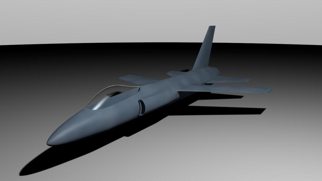
The rough draft...


... and the current version. My main goal here was intakes, which could stand to be pulled a bit farther from the fuselage. Intakes are a motherlovin' nightmare Rhino. They are easy as sneezing in Blender. They do extend into the body, but I have not added an engine face. You want the face of the inlets to be roughly the same area as the engine face, so with one engine, and two inlets, they need to be about half each. These probably aren't, but are probably pretty close.
I didn't like the way I cut my airfoils; I had a lot of unpleasant geometry around the root leading edge, and the root isn't thick enough for my taste. I do like being able to grab vertices and moving whole sections of the model into better positions. That's the kind of crap you need to get right the first time in Rhino, unless you want to rebuild and rebuild and rebuild and to hell with it it's fine. Working with Rhino for over 10 years has trained me to think about the final product before beginning. With concepts, I rarely use background images. Being able to shift wings and intakes forwards and back is a nice feature.
Though it looks like some horrible geometry bumping down the fuselage, it's the cloud texture that needs fixing. Adding noise to my specular gives it the realistic look of an fighter paint job.
The character sitting on nothing in the crew station is an imported MakeHuman 1.0 a7 mesh. So far I'm thinking crew stations are easier to do in Rhino because Boolean operations make control panels that fit the first time. Insetting, cutting, and pulling faces around for just the back section was aggravating. And having to crease nearly every edge. The canopy was a lot easier, though. And I like being able to separate faces into separate meshes.
Probably wont be doing too much more with this. Might experiment with making landing gear bays and doors, but that's about it. Maybe play around with the c*ckpit (does this place still sensor "c*ckpit?) And UV unwrapping and texturing.
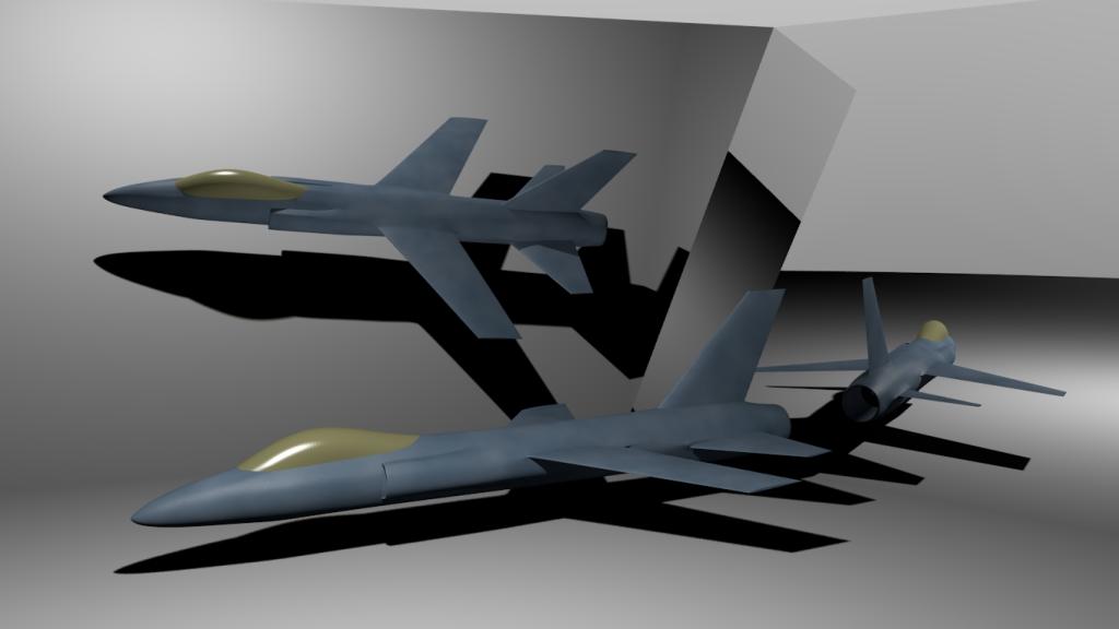
Stage 3 of my foray into the wonderful world of Blender involves much more complex shapes of current and future craft. I have in mind concepts of Generation 6 and beyond, pre- and post Singularity fighter craft. And what better practice that to use the YF-23 as a launching point?

I used background images for this one, so its the size of the YF-23. This is a drone, and many of my future fighters will be drones, remote piloted or intelligent, as that seems to be the trend, whether it's a good idea or not. There is also a little bit of my FD-120 [2D art I posted either last year or early this year]. I got plans to update the design for the FD-120, and the FQi-120 variant (the "D" designator indicates a drone command craft. The "Q" is for drone. I'm creating subdesignators "a" for pre-Singularity "Autonomous", and "i" for post-Singularity "Intelligent.")
The model is currently three separate pieces: The fuselage, the mirrored engine, and the mirrored wing. It looks acceptable as is, but eventually I want to the aircraft's main sections to be one mesh. I do have an engine cavity that the intake leads into. The engine ends up being smaller than the PW119 used in one of the YF-23s, but I'm not going to bother fixing it. Got a diffuser hump in the roof of the intakes for shockwave control, s-curve inlets, fuselage and intake chines for additional lift and vortex generation to delay or prevent boundary layer separation over the wing trailing edge at high AOA. I'm using fluidic thrust vectoring (using another airstream to deflect thrust as opposed to a actuated flap) which means I don't need that additional weight of tail stabilators. The wider wing is set back farther and will feature reflexed trailing edges. I'm not using the lambda wing planform as currently seen on the X-47B as that seems to be a stealth wing designed more for subsonic speeds than for high Mach in the 2 to 3 range that I prefer. The trapezoid planform is better suited, and placing it farther back along the engines allows it to squeeze inside a high Mach Mach cone (refer to the SR-71). I used a lambda on the FD-120, and that will be replaced.
I've been playing around in Blender for most of the year--working on a scene with a model I made in Rhino, and a MakeHuman character that's not ready for presentation yet--reviewing a lot of YouTube tutorials and learning quite a bit. Using Blender, I had to change my whole mindset on mesh making. I used Rhino as if I were drafting or sketching, so making models was relatively easy, though getting the shapes I wanted required a lot of precision up front, a lot of undoing and adjusting and redoing, and a lot of Boolean operations. I found Blender to be like sculpting. I had to get my mind around roughing out shapes, using modifiers, extending, scaling, and the dreaded pushing around vertices. I'm liking the results, the ease, and the speed. With Blender, I will be able to make the kinds of organic and flowing shapes and forms that I create with a pencil that I could never accomplish with (the old, old version) of Rhino.
Before I decided to delve into generating some concepts, I needed to review some tutorials on how to best make aircraft. Of the few that I choose, they were good launching points, but the wings lacked a definitive airfoil shape. [What I do like about Rhino is the mathematical precision of conic curves which allowed me to make pretty accurate airfoils.] I had to make some test articles.

That model was just to see how well I could knife an airfoil shape into faces and extend, and shape them into something that resembles a wing. I found that for the vertical stabilizer, it's best to apply the mirror modifier, and then cut the airfoil, instead if dealing with the unwanted scaling effect of cutting half of it on a mirrored half. I'm not working on this model any longer, so I'm not going to go back and round the nose.
That lead to the Generic Fighter test article.
fightertest_zps0f74f879.jpg
fightertest2_zps6ae91bed.jpg
The rough draft...
... and the current version. My main goal here was intakes, which could stand to be pulled a bit farther from the fuselage. Intakes are a motherlovin' nightmare Rhino. They are easy as sneezing in Blender. They do extend into the body, but I have not added an engine face. You want the face of the inlets to be roughly the same area as the engine face, so with one engine, and two inlets, they need to be about half each. These probably aren't, but are probably pretty close.
I didn't like the way I cut my airfoils; I had a lot of unpleasant geometry around the root leading edge, and the root isn't thick enough for my taste. I do like being able to grab vertices and moving whole sections of the model into better positions. That's the kind of crap you need to get right the first time in Rhino, unless you want to rebuild and rebuild and rebuild and to hell with it it's fine. Working with Rhino for over 10 years has trained me to think about the final product before beginning. With concepts, I rarely use background images. Being able to shift wings and intakes forwards and back is a nice feature.
Though it looks like some horrible geometry bumping down the fuselage, it's the cloud texture that needs fixing. Adding noise to my specular gives it the realistic look of an fighter paint job.
The character sitting on nothing in the crew station is an imported MakeHuman 1.0 a7 mesh. So far I'm thinking crew stations are easier to do in Rhino because Boolean operations make control panels that fit the first time. Insetting, cutting, and pulling faces around for just the back section was aggravating. And having to crease nearly every edge. The canopy was a lot easier, though. And I like being able to separate faces into separate meshes.
Probably wont be doing too much more with this. Might experiment with making landing gear bays and doors, but that's about it. Maybe play around with the c*ckpit (does this place still sensor "c*ckpit?) And UV unwrapping and texturing.
Stage 3 of my foray into the wonderful world of Blender involves much more complex shapes of current and future craft. I have in mind concepts of Generation 6 and beyond, pre- and post Singularity fighter craft. And what better practice that to use the YF-23 as a launching point?
I used background images for this one, so its the size of the YF-23. This is a drone, and many of my future fighters will be drones, remote piloted or intelligent, as that seems to be the trend, whether it's a good idea or not. There is also a little bit of my FD-120 [2D art I posted either last year or early this year]. I got plans to update the design for the FD-120, and the FQi-120 variant (the "D" designator indicates a drone command craft. The "Q" is for drone. I'm creating subdesignators "a" for pre-Singularity "Autonomous", and "i" for post-Singularity "Intelligent.")
The model is currently three separate pieces: The fuselage, the mirrored engine, and the mirrored wing. It looks acceptable as is, but eventually I want to the aircraft's main sections to be one mesh. I do have an engine cavity that the intake leads into. The engine ends up being smaller than the PW119 used in one of the YF-23s, but I'm not going to bother fixing it. Got a diffuser hump in the roof of the intakes for shockwave control, s-curve inlets, fuselage and intake chines for additional lift and vortex generation to delay or prevent boundary layer separation over the wing trailing edge at high AOA. I'm using fluidic thrust vectoring (using another airstream to deflect thrust as opposed to a actuated flap) which means I don't need that additional weight of tail stabilators. The wider wing is set back farther and will feature reflexed trailing edges. I'm not using the lambda wing planform as currently seen on the X-47B as that seems to be a stealth wing designed more for subsonic speeds than for high Mach in the 2 to 3 range that I prefer. The trapezoid planform is better suited, and placing it farther back along the engines allows it to squeeze inside a high Mach Mach cone (refer to the SR-71). I used a lambda on the FD-120, and that will be replaced.
Post edited by psCargile on
Tagged:
Additional credits
- Icons from Font-Awesome
- Additional icons by Mickael Bonfill
- Banner background from Toptal Subtle Patterns
© Scifi-Meshes.com 2001-2024
Posts
I guess that means it's not censored.
Anyway, now that we've established that, nice work so far. I really like the evolution of the concept and how you started off with a simple plane-shaped object and worked your way up to the futuristic drone. It's also interesting to note the differences in the software, even though I've never used Rhino and barely dabbled in Blender. I do know that Blender has some powerful sculpting tools, which are necessary for shapes like these.
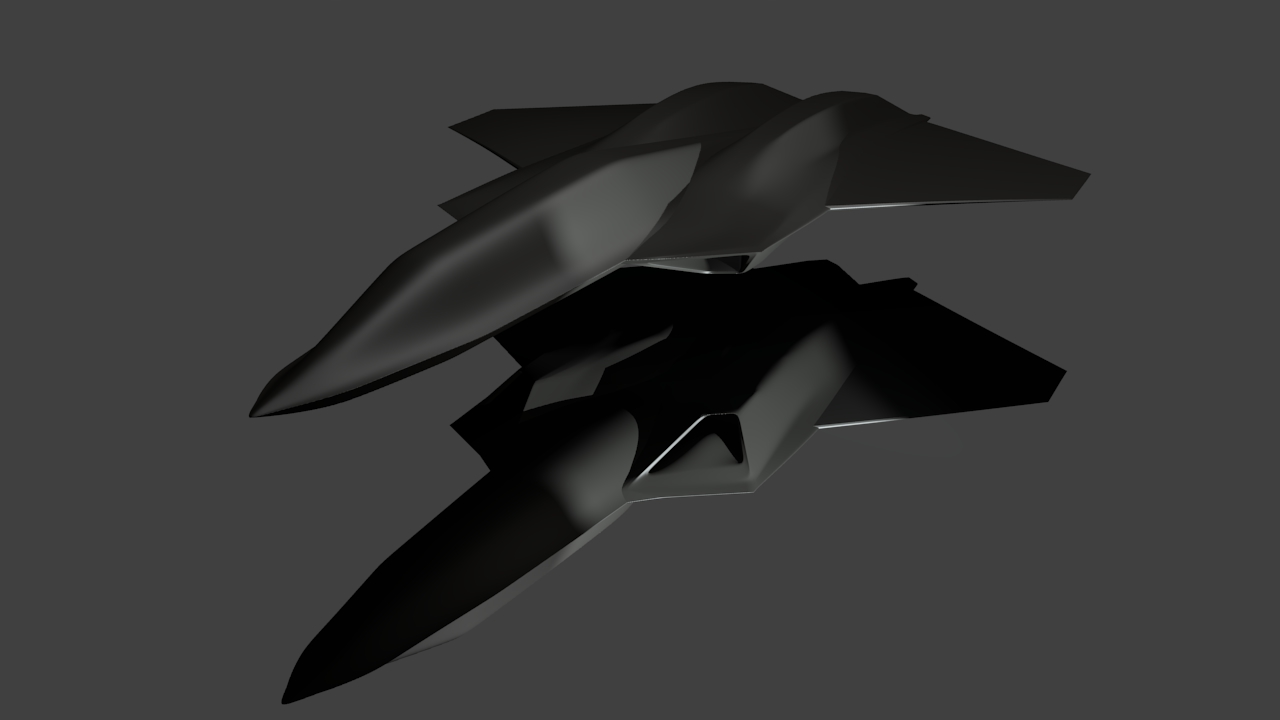
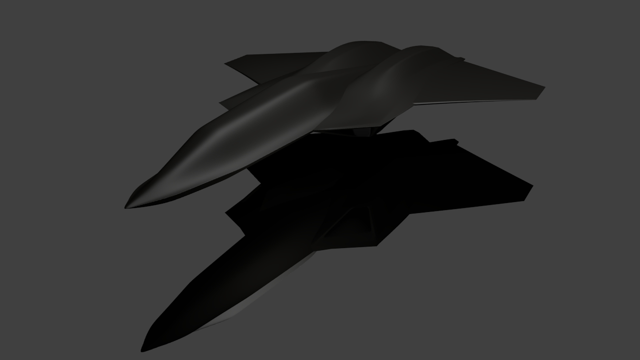
Here are some more views. Haven't done anything with the mesh tonight.
The next step is the engine. It will be easier to build a mesh around an engine, than to have to alter the fuselage mesh later after stuffing an engine in, or being forced to use a smaller engine, which isn't a big problem unless you want to use real world sizes. This engine is based on the PW119 dimensions easily found on the internet. I'm doing something a little different with my exhaust nozzle that is more akin to the F-117. This nozzle will blend into the wings' trailing edges. The area of the rectangular opening is the same as the exhaust duct for equal pressure distribution (over 11 ft wide and 1 ft high). The plan is for thrust vectoring and closing off the outer edged of the "fan" for greater pressure in the center.
The inlet will come next.
Yes, you should definitely build the fuselage around the engine. (I know that much
I really like the design of your plane, it's nice to see it from a few more angles.
Usually when I sketch a top plan view, I'll draw a rough idea of the Mach angle and the engine first, so this is a 3D version of that process. In Rhino, I made some human figures, and I would import my pilot to design the fuselage around. For the Generation 2 jet above, I lucked out.
Oh yeah... I use X-Plane and it's PlaneMaker and AirfoilMaker to build experimental aircraft. You learn things trying to get planes to fly reasonably well. The Gen 2 jet is based on a simple experimental I was working on last year in X-Plane. One goal is to develop these ideas into flyable sim aircraft.
By the way, i recognise the physics of the shockwaves, i know it to be the reason for the very blunt nose on the space shuttle, to widen the cone so it doesn't slice through the wings.
Landing gear stand-ins. I was looking at YF-23 gear pics and noticed that the main gear wheels are reversed with the brakes on the outside. The wheel looks very much like the F-15's, and since McDonnel-Douglas was a partner, I wouldn't be surprised if they were.
Not too happy with the way the gear doors came out. I have to set the Crease to 1 on all edges of the door to avoid weird intersecting geometry, which doesn't match the creases on the engine nacelles. I'll need a new approach and have an idea on what to do. Good thing I saved it as a new file. In Rhino I can rotate around an axis selected from two points, and if this were a Rhino model, I could swing the door out along the top hinge line. Not sure how to do that in Blender yet, without rigging bones.
I usually dump images at Photobucket, but it seems like none of those services want to allow direct linking to the images. I want to show you the images, not the host. Then I remembered I still have a Tripod account from years ago (1998?), and voila--no album BS.
I'm lighting the scene with a point light with shadows, two fill points lights with no shadows, and an area light aimed at the side as an indirect source as Blender's Indirect or Environment lighting effects increased render time and produced worse results that the area light.
It's just all kinds of bad. I've an idea about what I need to do.
Some work on the nose gear. I do like the deformations I can do in Blender to get the correct shapes on the strut.
Great reference photos at yf-23.net.
But on to the other...
For a jet engine to run efficiently, it's important that air striking the compressor face is a uniform pressure and speed. As I've stated in the initial post, for a more accurate designed look for your model, you want the inlet cross-section to have the same area as the compressor face (or a little larger, as there is going to be unwanted boundary air that need to be bleed overboard). Blender makes that easy without having having to do math, by clicking on the Area option under Mesh display. Select the face you want in edit mode, and the area is presented in real hard to see numbers unless you jack the DPI up in the user preferences. :mad:
To make the inlet, I added a plane, and scaled it to match the surface area of the face that represents the compressor face. I placed the plane some arbitrary distance away from the engine, then extended the inner edges of the lip of the engine--because I'm only making the internal geometry of the duct. Bridge/lofting deletes the face of the plane, and adding a crease value of 1 maintains the geometry. Not extending the lip of the engine and lofting to the plane creates a geometry that doesn't loop cut well. I loop cut several sections into the round duct, so that it flows nicely when using proportional editing to lower the inlet face. Technically, radar stealth calls for a serpentine duct to hide the compressor face as whirling blades throw back a lot of radar energy. This means you want at least two bends, and for it to be effective, the duct needs to be long enough for shallow bends. After trying many bends, I decided not to worry about that for this project as my duct is too short, and the bends too extreme. The compressor face will just have to be exposed.
For shock wave control, I took my Mach cone, and aligning it with the square intake cross-section, and extended the upper edge to the cone's point. At 2.5 Mach, a shock wave will extend from the upper lip to the lower, as well as forming at the lower lip and bouncing shock waves down the duct. Jet engines cannot operate in supersonic airflow and shock waves serves to slow the air down to subsonic speeds. I'm not an aerospace engineer, so I'm not actually designing an intake system, I only want to get the appearance close to reality.
I would really rather there be no sharp edges in the duct, but lowering the crease values presented problems where the square merges into a circle.
Intake duct placement
The inlet's main job is to provide subsonic air to the engine. That means they can't be placed anywhere an artist decides they look cool. Intakes set back on the top of a fighter you expect to maneuver, will starve for air at a high angle of attack climb. That's the worst time you want your engines to stop producing thrust. If they must be on top, they must be on the nose where the body of the aircraft will not block the air flow. The best place on fighters is where they always are: on the side, or on the belly, where a number of different maneuvers will not restrict air flow.
Useful links:
http://www.airspacemag.com/military-aviation/how-things-work-supersonic-inlets-35428453/?no-ist
http://www.grc.nasa.gov/WWW/K-12/airplane/short.html
Shadows make the tire look flatter than it actually is. I like the lattice deform modifier.
Whew...What a challenge.
I checked that in Excel, and that answer is in radians, so it's not really a coordinate that Blender uses. It could be treated as a polar coordinate and converted to Cartesian, but building of a cone is far simpler.
Blender can use degrees or radians, just put “d” or “r” on the end of the number or expression.