Greetings!
Welcome to Scifi-Meshes.com! Click one of these buttons to join in on the fun.
Quick Links
3DMPS Modular Space Platform
MSP Modular Space Platform
In a previous WIP I set out to create a more realistic space sandbox for my story world. Sadly, I got side tracked and began building a dropship that was further towards the Fiction of Science Fiction. The original intent was to build a fleet of vessels starting with the most basic need of space exploration, surface to orbit transfer of payload.
In this WIP I will stick to my original plan; more science in my scifi.. I'm calling this the MSP Project. I will design a space platform that is completely modular not only in function but also within sketchup (my 3d program). All the parts will make up a massive component library. The parts will then be put together into space capsules which themselves will be components and in turn can be put together to form a range of space platforms from space stations to deep space exploration vessels. All the modules will be able to be launched into space via rocket launch vehicles or space shuttle like vessels. Once in space they can be easily interconnected and placed in service. I will start with the airlock module.
***Will have most recent pic here***
Post edited by alleyviper on
Tagged:
Additional credits
- Icons from Font-Awesome
- Additional icons by Mickael Bonfill
- Banner background from Toptal Subtle Patterns
© Scifi-Meshes.com 2001-2024
Posts
The air tight doors will plug an opening about 4 feet in diameter. The doors are designed to open in to the module and will not open if the pressure on the outside is less then that on the inside. Opening the doors is simple but still must be done manually (Automation equals more weight). A centrally located handle serves to unlock and open the doors. From the outside this handle must be pushed and turned while from the inside it must be pulled and turned to unlock and open. A small 7" diameter porthole window allows crew to observe docking operations.
Holy crap Mikey! I was doing research on the internet to see what kind of docking systems Nasa was developing or using to try and imagine what the future varients would look like. I thought that the low impact module berthing system was an actual Nasa design! So, when I did a search for images of berthing systems/space docking etc I came across your pics. Thinking it was someone's model of a real design I incorporated it. I really thought there was an actual Nasa design out there called a LIMBS. I didn't want the old school probe and drogue design and the LIMBS looked like the future way to go. I really hope this doesn't mean I stole your design bro, I worked really hard on it.
Crap, I really thought the LIMBS was a real Nasa design. After doing tons of research on how space docking works, I google image searched for images of the most modern looking designs. Usually I save the images right to my drive and reference them later when I get stuck. Here's some of the images I had referenced (The ones I used the most and can remember what keyword I used to find them).
I knew about the low impact docking system. In your pic it says low impact module berthing system which I thought sounded more like what I needed since I'm working with modules so VOILA, I'm an idiot that thought your model was a Nasa design. Kudos to you I guess. My design is basicly just an ILIDS system but it allows for fluid transfers between modules like a Berthing system without using the much larger outter ring. My fluid exchange mechanisms are built into the ring not sitting between them. So ILIDS +berthing system, here's a model some Nasa fan made of a system that says LIMBS, makes sense to me, I'm an idiot.
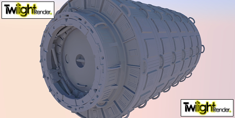
The 8' modules will be used for things like docking appendages, nodes, and airlock parts. I also plan a standard 12' diameter module to be used for things like command, service, habitation, spinning sections, and utility. I guess I could go as big as I want, but for now I am only going as big as the 12' modules as I have a delivery vessel in mind with a cargo bay not much larger then 12' in diameter.
This may look simple for those who use more powerful modeling software. I think most sketchup users can attest to the fact that adding detail on curved surfaces with this program is difficult, especially if you want it seemless. Each full circle is 600 segments, each segment 1/2 inch long. Tiring.