Greetings!
Welcome to Scifi-Meshes.com! Click one of these buttons to join in on the fun.
Quick Links
3DConstructing a ConnieA2
yep its ANOTHER TMP era Enterprise 
this is a long-term project, the ultimate goal of which is a complete inside & out as-built workup,
complete with structural, electrical, environmental, plumbing, etc... the whole shebang!
ive modeled this many times, in both 2d and 3d version, but this one is a brand new version.
this one is slightly modified so that all parts internal and external as known fit together.
for now the only plans i have for the actual interior layouts are going to be based around the filming sets, i'll decide what to do with the rest of the decks later once the known sets and rest of the structural details are finished.
and now on with the show!
059.png
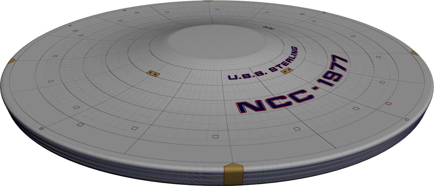
I've only just completed the geometry on the major components this weekend, these first images are just some preliminary renders for some color testing. i plan next to get into some more of the outer hull details next, but the preliminary deck layouts are already done. i'll show more of them next time once ive had a chance to start up some cutaway views.
untill then, here's a few profile shots, hope you like it!


this is a long-term project, the ultimate goal of which is a complete inside & out as-built workup,
complete with structural, electrical, environmental, plumbing, etc... the whole shebang!
ive modeled this many times, in both 2d and 3d version, but this one is a brand new version.
this one is slightly modified so that all parts internal and external as known fit together.
for now the only plans i have for the actual interior layouts are going to be based around the filming sets, i'll decide what to do with the rest of the decks later once the known sets and rest of the structural details are finished.
and now on with the show!
059.png
I've only just completed the geometry on the major components this weekend, these first images are just some preliminary renders for some color testing. i plan next to get into some more of the outer hull details next, but the preliminary deck layouts are already done. i'll show more of them next time once ive had a chance to start up some cutaway views.
untill then, here's a few profile shots, hope you like it!
Post edited by anystar on
Tagged:
Additional credits
- Icons from Font-Awesome
- Additional icons by Mickael Bonfill
- Banner background from Toptal Subtle Patterns
© Scifi-Meshes.com 2001-2024
Posts
Are you losing your mind?
To build interiors and exteriors will will make this wip a looooooong one. ThereAâs a wip like this at Foundation 3d. Take a look that and you can get some inspiration and refs too.
About the mesh, the scondary hull is a bit segmented for now.
i was fighting the insomnia-monster last nite, here's a preliminary look at my jumping off point of the major elements structural configuration.
probably, or i will by the time its done!!!:cool:
several months back i discovered a thread somewhere of an original enterprise deckplan workup, it was part of my inspiration for this, (i lost track of the thread, if you could point me to it i'd be appreciated.
the other thing that got me into this was all the new reference material on the filming model recently released. hundreds of high res photos from Mark Dickson several sets from different periods in the models life.
Every time i see a new pic of this beauty i just fall in love with it all over again!
sooooooo, here we are!
the whole project is still in AutoCad, and I had a hard drive meltdown a few months back, since then this is the first time ive gotten into any 3d stuff with cad, and so my settings are still funky :mad: i also tend to keep some settings turned down untill render time, or else autocad gets angry with me and throw a tantrum! LOL
eventually i will probably move this over to max, but my skills in that are so not up to par
I was talking about this one: Star Trek - Enterprise 1701-A Refit - bmckain - Foundation 3D Forums Is that youAâre talking about too?
Basil is doing the interiors for the Akyazi: http://www.scifi-meshes.com/forums/3d-wips/13014-akyazi-akula.html. For sure has things in common with the Ent-A.
but the thread i still hav'nt "re-found" is one of the original enterprise, a full 3d buildup based on (i think) the old deck plans by Franz Joseph
Star Trek LCARS Blueprint Database - Star Trek Blueprints: General Plans: Constitution Class: U.S.S. Enterprise
I came across it once, then forgot to bookmark it.
if i come across it again i'll be sure to insert a link
i remember reading he wanted to convert the mesh into a html walkthru at deck level, if that helps jog your memory
bingo, and the link there to the w.i.p. of the C2 over on the trek bbs was a nice lil xtra too! or maybe a "oh-crap, what have i gotten myself into" :cool:
ill pop the direct links to both in here so ill be sure not to lose them again!
original: NCC-1701 USS Enterprise Deck by Deck - WIP - 3D Buzz
refit: WIP - TMP Enterprise, deck by deck - The Trek BBS
(on a side note, i have a story eerily similar to CTM's
I too began in autocad as a draftsman evolving to designer/engineer, and as well i began working in autocad (R11 was my first copy), back in the day when you booted your pc THEN if you wanted to use it you started up windows... geez, how did we ever get anything done back then? haha.
these days i work primarily in Autocad 2008, and was gifted a copy of Max9 for my birthday last year (i'm such a noob in Max though, i'm still YET to sit down and actually school myself on how to properly use it). i keep going back to Cad because of my background, i keep thinking "its just not accurate" or in other words i'm just used to seeing zero-thickness lines with dimension leaders all over the damn place... lol
anyway, enough about me and my stubbornness for now. back to the show
as for my version... i've spent the day digging through screencaps trying to decide where to begin. i believe i will be doing more work on the nacelles and other "non-livable" areas and components untill i make a decision on how to dig into the other areas.
on a related note, i will be relying heavily on screenshots to build my "innards" but these deck plans will be my fallback reference Star Trek LCARS Blueprint Database - U.S.S Enterprise NCC-1701A Deck Plans
i dont think i have ever come across any other similar breakdowns for the refit ship. and every time i think about it, it just seems like there "should" be more out there somewhere... i mean this IS the most beautifull ship ever crafted isnt it?
anyone know of any others?
Yes it is.
I'm really looking forward to this since the E-A seemed to have the most personality to me.
YouTube - Life-Size USS Enterprise - Star Trek TOS TNG - TOUR: Deck 5 VRML
It's the TOS Enterprise based on Franz Joseph's blueprints, but it gives a good impression of the scale of the project you're undertaking. I'm looking forward to your progress on this because it's always been a dream project of mine as well. You'll have a lot of conjectural decisions to make, and I'm betting that justifying some of the known interior sets to the exterior shapes will prove a challenge (i.e. the photon torpedo room), but I can't wait to see where you go with this. Best of luck!
i.e. - a true Refit, or parts from the A, or "which" A version to use... lol
to me, i think what did it was the "introduction" itself. with the exception of Spaceball-1
if i'm not mistaken that's the same build as the one on the trekbbs!
as for mine, i'm already outside of the box, my craft has 23 decks. probably due to the fact i'm not using the usual 9' deck heights... i just dont see that as how it would be done. most living spaces are justshort of 8', although may engineering and mechanical spaces have been aloted just under 10' dimensions (both floor to ceiling measures). i think of it this way, take a tape measure to your house or office, you dont have ceilings that tall there do you?
and when i plug in the cutaway image from the deck plans you can see where we start to differ. you can also see portions of my model are slightly slimmer when compared to the ref image.
i HAVE found a place to start in though, i'm still going to finish out the nacelles first. then, instead of taking a deck-by-deck approach, i'm going to instead tackle it component-by-component.
first will come the warp core and impulse engines, once that is done i'll continue to build compnents and add parts and systems as need.
before i can get into the nacelles though, it only today dawned on me that i've never seen any canon images of the "guts" of them. I think these 2 images are the only cutaway views ive ever come across of these type nacelles. :eek:
i'll just have to dig into my reference archive for other nacelle innards to try and piece a configuration together. (unless any of you know of a direction to point me in!!!) i'll see what i cant dig up, and post again once ive gotten something more built up on them!
http://www.cygnus-x1.net/links/lcars/blueprints/miranda-class-starship-uss-reliant-ncc-1864-sheet-11.jpg
http://www.cygnus-x1.net/links/lcars/blueprints/miranda-class-starship-uss-reliant-ncc-1864-sheet-14.jpg
Good luck with your project...or rather patience
ooo! my curiosity is peaked! :devil: i'd love to see what you came up with, ty
ty, i hope i dont dissapoint!
Here's the link to the schematics I mentioned in a previous post. Like I said, they aren't completely accurate and looking at them now there are a lot of things I'd change, but they sure were fun to make.
RapidShare: 1-CLICK Web hosting - Easy Filehosting
I tossed my cutaway of the TOS Enterprise in there as well, just for good measure. I'll leave them up for a while in case anyone else would like to download them. I hope they help.
Not a problem. Luckily, I knew which CD (of the seemingly hundreds I have littering my computer workspace) I'd saved them on. Like I said, they're not perfect. I squeezed a 24th deck into both because I didn't like the idea of the ships having an odd number of decks. Don't ask me why. I really don't know. There are other things I'd change now, too; but when I made them (2002? 2003?) I was very proud of them. If they provide you with even the smallest assistance, then I'm happy.
If anyone else wants to download them, please feel free. I'll leave them up on Rapidshare for a while.
We now return you to our regularly scheduled thread, already in progress.
he did this while i was at work this afternoon, lol
according to his numbers here, if you actually built this whole thing it would be 5' wide, and almost 22' long!!! WOW
On the other hand, how cool would it be to make a Connie that big out of Legos.
well, ive begun working in the warp core
in order to make it fit like what is seen on-screen
the first of which is that the main off-shoot to the nacelles (and therefore main engineering itself) ends up 2 decks below what all the available cutaways/scematics show...
first, on mine-
the other solution i'm tossing around is to simply leave it as it lies, and model in the hull curature anyway. doing it this way i could "fudge" it all by calling the outlying areas some sort of fluid or particulate matter storage, justifying the curvature.
the only downside to this solution is that it effectively ruins any hope of modeling the storage areas/ hangar decks as shown in the matte paintings.
hmm, as i was looking at that matte as i uploaded it, i looked a little deeper... aligning all the decks perspectively, the roof of that image is only 1 deck above the flight deck (my eye always tricked me somehow, and i thought it was another deck or 2 higher), anyway it would make up what i've shown as my floor for main engineering...
you look at something a thousand times, and can still miss the meaning! i guess this means im going with option number 2!!!
here's a couple more vantages
i also ported it to Max today while i was trying to decide what to do. it doesnt translate very well, but hey- its a start!
oh well, it's about time to fire up the grill, so thats all for now!
Well, like I said, this is going to be a challenge and it looks like you've found the first of many. Of course, the real curse here is that the set designers never intended thier work to be so closely scrutinized and matched to the exterior of the ship. In my opinion, that gives you license to make some creative decisions, including dropping Engineering a few decks down if you need to.
This is getting more interesting with each new posting from you. Can't wait to see what happens next.
It's not easy deciding wether you want to duplicate exactly what was on screen (which often proves impossible), make it fit as closely as possible or adjust it so it makes sense...
I too say, take your bit of artistic license. Afterall, we want you to keep your sanity and keep going, so we can see more!
If you need help with max at some point in the future, there are a lot of max users here, and quite a number willing to help (myself included)
I never realized it too. Your alternative looks good Dan.
Here's an example of my troubles. when working in 3d with AutoCAD smoothing is automatic as it follows its 2d engine: a circle is a circle is a circle! and a line is a line is a line. when these objects are converted to Max or 3ds there is no baseline for smoothing, and the only thing that i have found that will help with poly translation for the max file is overall size of the objects. none of your display settings/smoothing. and the only program setting for object subdivision during creation "horizontal or vertical isolines" seems to have no effect at all. :mad:
also the .3ds export is of no use at all, objects exported in this fashion are broken down in such large and angular portions that no detail is preserved. and .dwg objects imported in Max end up super-high poly, the detail is there but the file is HUGE :mad:
here's a couple screenshots of what i'm talking about.
the original AutoCAD version
the .3ds exported version (3 different smoothing settings used on import, back right is 30%, front is 0, and back left is 75%)
and this is what happens when the original .Dwg is imported to Max
i have a friend coming to visit next week that hopefully can help me with this. but untill then, have any of you had any experience with this?
The attached pic shows the better parameters (at least until now) that I found.
About the conversion itself, Deep Exploration with 3dsmax plugin, is how I get better results.
ill give that a shot and see what i cant come up with. if all else fails though, i've blueprinted this thing about 20 times, and made about 5 different 3d versions of it so far! so in the worst case scenario where i have to completely re-build it i would think it shouldnt take too long to re-create
I don't know AutoCAD at all, but is it possible to collapse/freeze the mesh? Exporting then should export the exact polygons.