Greetings!
Welcome to Scifi-Meshes.com! Click one of these buttons to join in on the fun.
Quick Links
Local TutorialModeled lettering - The goatboy method
I've had several PM's in the past about my lettering technique, so I figured I put up a VERY basic tut on the way I do it. a basic knowledge of max is required to understand this. the benifit to my method is that you dont have to muck about with mesh errors and such as you do when actually cutting the lettering into your mesh (as some do) and you can easily re-label your ship or whatever
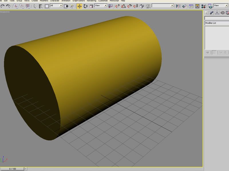
first things first, you need some geometry to wrap too. I'm using this cylinder, obviously in your work it will be a nacelle or something.
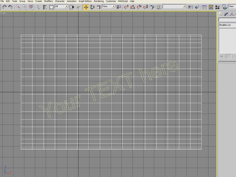
your text should look something like this now
now, add the text you wish to wrap. convert to editable poly, or mesh if you prefer. I prefer poly modeling. notice that I have the text rotated here a bit to wrap in a more interesting way around my cylinder for the sake of the tut
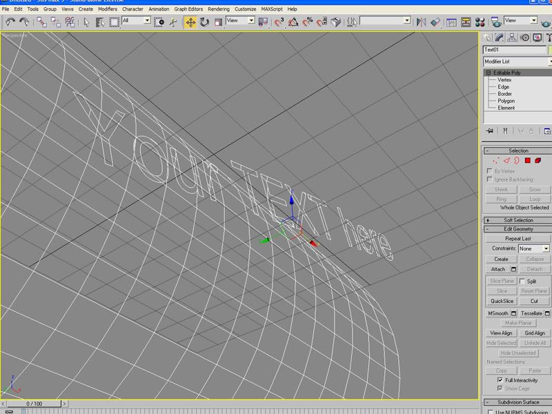
now, move your camera (in user mode, NOT perspective) to a spot that aligns the text in front of the surface you want to wrap too. like so.
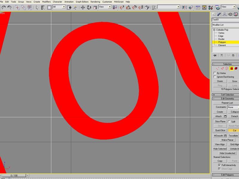
now switch to wireframe (if you arent already) and begin using the cut tool to cut lines matching the mesh behind the lettering. in the case of vertical and horizontal lines as in this case, you can use the slice plane tool to speed things up drasticly. once all the edges are added move on to the next step. you can just make out the cuts i'm making here.
now, align the camera as best you can to place the object directly behind the text and go to the Create tab, in the rollout where it says standard primitives, select compound compnents. on this screen you will see a box labeled conform. select your text, there are four options listed below the wrap to button, select the move tick box, then hit the Pick Wrap-to object button and click your cylinder. this may take a few seconds, on a high poly mesh with a complex font this can take a few minutes. now, the text and cylinder should be one object, and the text is wrapped.
right click the new combined object and click the convert to poly button, then select the element sub-tree on the right-side object rollout, this should automaticly highlight your text. click the detach button and your almost done.
now, I prefer to rightclick the new text object and gop to advanced, and set the object NOT to cast shadows, this avoids alot of trouble later, esspecially if your using shadow maped lights.
now select your text and you can move it manually VERY close to the surface of the cylinder. from all but the most extreme closeup and angle it will apear to be painted on. now you can assign a texture to the text and render.
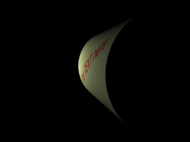
you should end up with something along these lines.
I hope I didnt make myself to foggy on this.
first things first, you need some geometry to wrap too. I'm using this cylinder, obviously in your work it will be a nacelle or something.
your text should look something like this now
now, add the text you wish to wrap. convert to editable poly, or mesh if you prefer. I prefer poly modeling. notice that I have the text rotated here a bit to wrap in a more interesting way around my cylinder for the sake of the tut
now, move your camera (in user mode, NOT perspective) to a spot that aligns the text in front of the surface you want to wrap too. like so.
now switch to wireframe (if you arent already) and begin using the cut tool to cut lines matching the mesh behind the lettering. in the case of vertical and horizontal lines as in this case, you can use the slice plane tool to speed things up drasticly. once all the edges are added move on to the next step. you can just make out the cuts i'm making here.
now, align the camera as best you can to place the object directly behind the text and go to the Create tab, in the rollout where it says standard primitives, select compound compnents. on this screen you will see a box labeled conform. select your text, there are four options listed below the wrap to button, select the move tick box, then hit the Pick Wrap-to object button and click your cylinder. this may take a few seconds, on a high poly mesh with a complex font this can take a few minutes. now, the text and cylinder should be one object, and the text is wrapped.
right click the new combined object and click the convert to poly button, then select the element sub-tree on the right-side object rollout, this should automaticly highlight your text. click the detach button and your almost done.
now, I prefer to rightclick the new text object and gop to advanced, and set the object NOT to cast shadows, this avoids alot of trouble later, esspecially if your using shadow maped lights.
now select your text and you can move it manually VERY close to the surface of the cylinder. from all but the most extreme closeup and angle it will apear to be painted on. now you can assign a texture to the text and render.
you should end up with something along these lines.
I hope I didnt make myself to foggy on this.
Post edited by Gothic_Goatboy on
Additional credits
- Icons from Font-Awesome
- Additional icons by Mickael Bonfill
- Banner background from Toptal Subtle Patterns
© Scifi-Meshes.com 2001-2024
Posts
look a few paragraphs up from the bottom most pic.
though it cant be repeated enough, if your lettering is casting shadows it will turn out ugly under most lighting rigs, even when its VERY close to the mesh
oops, missed it ^_^
This is my just dessert for NOT registering the program!
UPDATE: I've been using Max 8 for some time now, and I've noticed that materials have to be assigned to the parts you're modeling, and then again to the original piece, or this method turns the entire piece the color you're using. With markers on starships, I assign the material beforehand, and the original piece gets its material assignment when I'm done.
I'm doing a Connie I rebuild following a hard drive crash, and I can't prevent it from conforming to the INSIDE edge of the nacelle in the model.
Select and copy the polygons your text goes on into a new layer, flip them, and extrude inwards. Press m to merge the points, which connects the faces into a solid box. You should now have essentially a piece of the surface hull with some thickness to it, where the outer surface matches the whole mesh totally.
Create your text label, flip it, and extrude it into the piece of hull, but not through it, then press m again to make the (really raised) letters into solids. Select the hull plate, and boolean subtract it from the letter staves. select all the faces other than the ones just created by the boolean operation, and delete them, then flip the text so it faces back outwards. Submerge the letters under the hull surface by the tiniest bit your editor will allow, then raise them through the surface by beveling them back up. (I use this for any lettering regardless, to make sure the text really is part of the model rather than floating beside it - it makes for some extra polygons, but that's not really a problem once you're not dealing with a budget on those.)
sP
Edit: Chris, it sounds as if your object is inside out - even with double-sided polygons enabled, IME they still have a "true" outside that's used when something interacts with them. Try flipping the faces of your object?
Mirror the object before to use the conform.