Greetings!
Welcome to Scifi-Meshes.com! Click one of these buttons to join in on the fun.
Quick Links
3DFast Freighter - SFS "Crate"
 Tinukedaya182
Posts: 271Member
Tinukedaya182
Posts: 271Member


Hello everyone,
after years and years I'm trying to do some graphics again. And since I don't have access to 3D max anymore, I've started to learn Blender. I'm not sure this is a material worth posting among all those awesome things on this forum, after all it's a "learning blender" project but I thought it might actually make me a bit more motivated to work on it further, even when I struggle with the basics.
So without further delays, here comes another of my Solar Federation Ships. The small but fast freighter which I have no name for yet (suggestions are welcome).
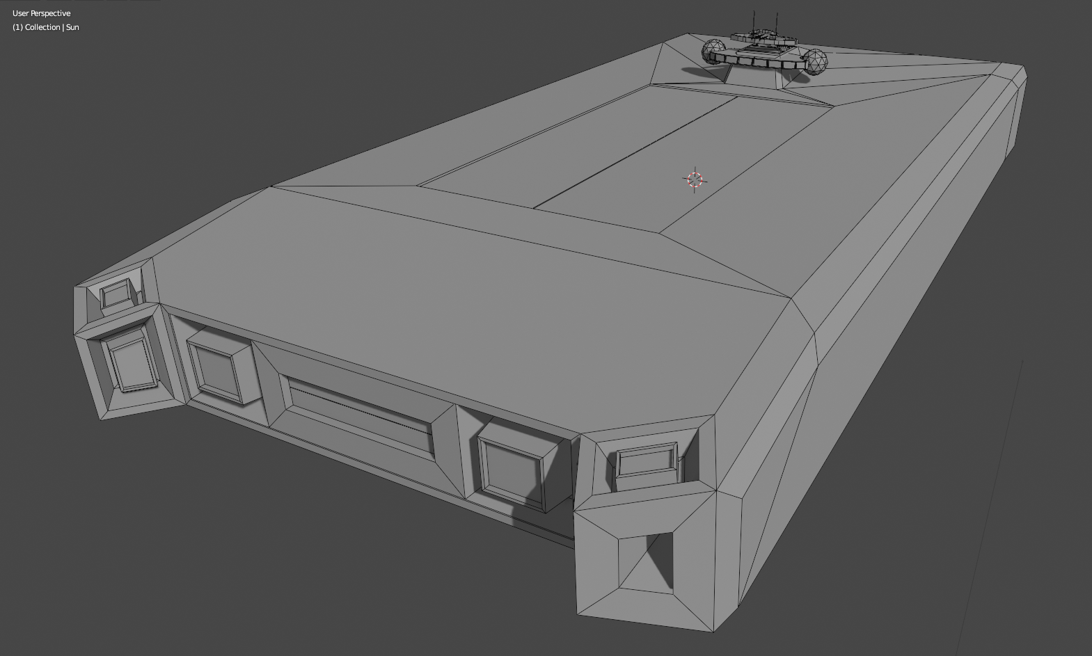
So far I blocked out the basic shape and gave a few details to the bridge.
after years and years I'm trying to do some graphics again. And since I don't have access to 3D max anymore, I've started to learn Blender. I'm not sure this is a material worth posting among all those awesome things on this forum, after all it's a "learning blender" project but I thought it might actually make me a bit more motivated to work on it further, even when I struggle with the basics.
So without further delays, here comes another of my Solar Federation Ships. The small but fast freighter which I have no name for yet (suggestions are welcome).
So far I blocked out the basic shape and gave a few details to the bridge.
Post edited by Tinukedaya on
"Any sufficiently advanced technology is indistinguishable from magic." - Arthur C. Clarke
Cruiser - SFS Suricata --- Freighter - SFS "Crate"
Cruiser - SFS Suricata --- Freighter - SFS "Crate"


Additional credits
- Icons from Font-Awesome
- Additional icons by Mickael Bonfill
- Banner background from Toptal Subtle Patterns
© Scifi-Meshes.com 2001-2024
Posts
It's worth posting. For one thing, as you say, you're learning the software and there are a lot of people here who can help you. Also, I wouldn't worry too much about comparing your stuff to what others are posting. You have to do your own thing and keep on leaning. I think everyone here is still learning.
Damn it's tough to get used to blender. It's more then 10 years since I was doing graphics on more "regular" basis. Yet my fingers keep pressing the keyboard in a way they were used to in Max. And keep wondering why it doesn't work.
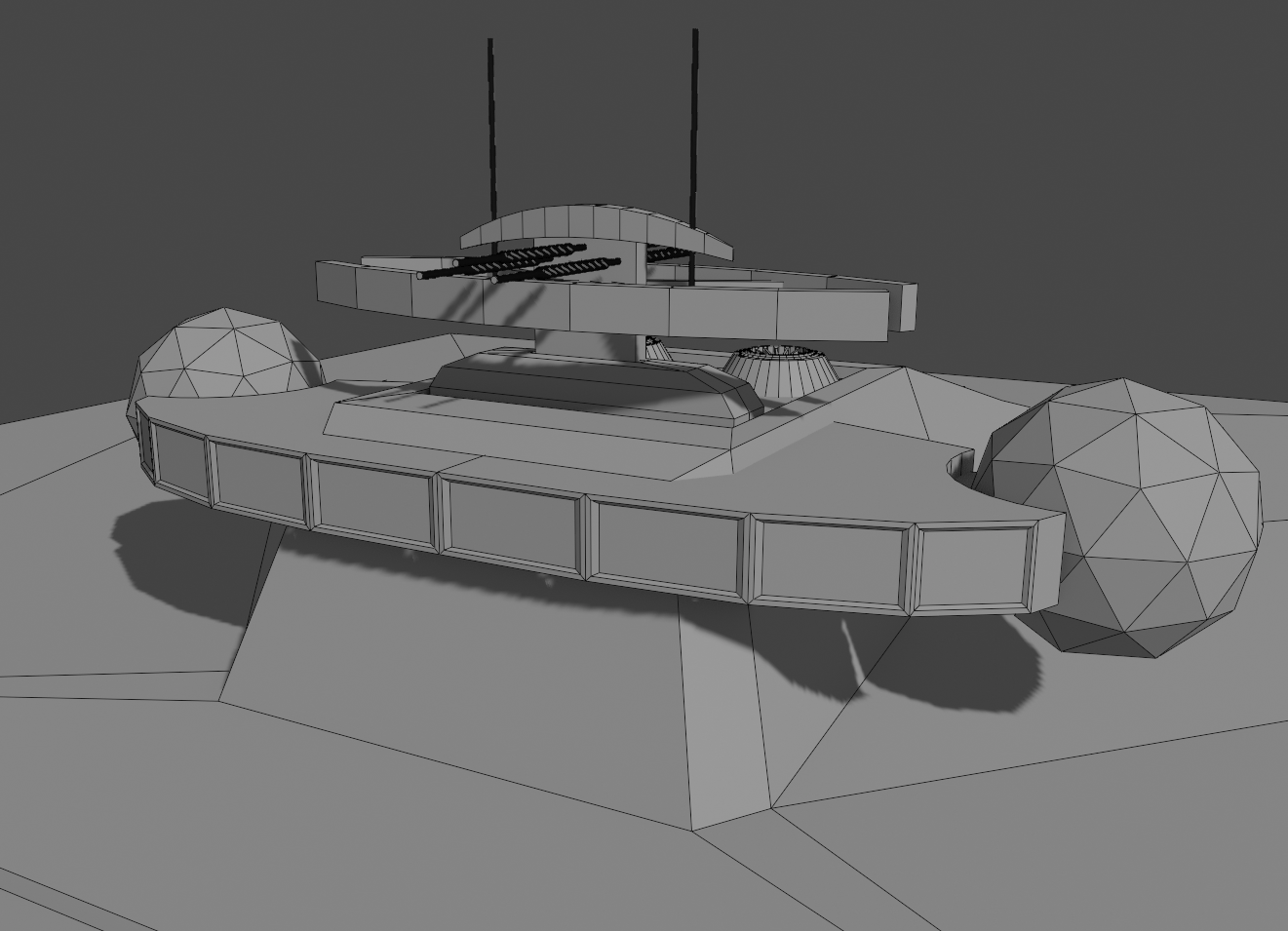
Anyway. I'm playing around with some detailing. Keeping the style I have on my ships, I struggle to find a way to do the pipes... I watched some tuts on the topic and it turned out quite ok I guess..
Cruiser - SFS Suricata --- Freighter - SFS "Crate"
Looks like you're off to a good start so far.
Here's the steps for a simple pipe.
Add a plane. As you know it's going to be facing up, so 7 number-key for top view. If you do any scaling and rotating, ctrl-A and apply rotation and scale. Many a Blender headache is caused by models not scaled to 1 in all axes, or not to 0 rotations. Always remember ctrl-A.
Edit mode, press 1 for verts, and delete one of them. Select the corner vert, ctrl-shft-B to bevel, slide the mouse for size, and roll mouse wheel for number of verts in the bevel. A window pops up along the bottom where you can adjust the parameters of your bevel.
Object mode, Object menu, down near the bottom, Convert To curve from mesh/text.
Over on the properties tab, select the curve icon, and you'll have the options for the curve. It should already be defaulted to 3D, fill mode as Full, Radius checked.
Open up the Bevel tab and give it some depth and resolution. A resolution of 9 is usually good. But for thin pipes that are ever going to get a close up, a lower number is fine, especially if you are going to use a subsurface modifier, or if it is such a small detail that it doesn't matter. Under the Geometry tab you can play with offset, how far away the mesh is from the curve, and extrude, which will give it width in the local z direction.
When you are happy with results, convert to mesh. Once it's a mesh you can add a solidify modifier--don't forget to shade smooth and auto smooth the normals in the object data properties tab. Or in edit mode you can cap the ends, add loop cuts to select faces to extrude or scale for different thicknesses.
Taking that to the next level, you delete three verts from a plane (or selecting all verts, M, and collapse, and that will leave you with a single vert) and start extruding the remaining vert to lay out your pipe path. And because you are extruding, you can extrude in any direction. You can select a number of corner verts to give them all the same size, or each one for different sizes. For pipes that will have a tight 90 degree turn, you probably want to use as few vertices as possible to define the curve. When the mesh is created you could end up with overlapping faces in the inside corner. And if auto-merge is toggled on, you may end up with bad topology. Poor geometry gives poor shading. Also, if you want pipes to conform to the geometry of your mesh, in edit mode you can select the verts that best follow the path of the pipe, duplicate them, P to separate, then you have a new mesh you can edit into your preferred pipe shape.
If you try to create junctions when you are extruding verts, you have to switch from 3D to 2D, but when you convert to mesh it creates two linked meshes (as one object) intersecting at the junction, which will not make nice modifier bevels, and will require some tedious mesh clean-up. Easier to activate the Pipe Joints add-on in the preferences and play with that for pipe intersections.
Of course, there are many ways to make pipes, I find it easier to edit the "skeleton" of the pipe than play around looking for the best cursor position to use the spin tool. However, this method only creates circular (unless you extrude) pipes. For creating something like a waveguide, that's another method.
I see I'm not the only one with the muscle memory under my skip... Good to know. I begun to feel like a crazy person.
@psCargile Thanks for this tut! The pipes I have there are actually a result of the same technique. I saw it somewhere on the net.
But do not feel like typing it was a waste. Because I was doing two step in different order and it caused me a huge headache. And the result was not good anyway.
See, I was doing the link of verts as you called it and managed to do all the other steps to make a pipe. But the result was very sub-optimal. The reason was (just tried that in blender) I didn't bevel the corners on the line. I only made a shape and then converted to curve. I wanted to bevel the corners only on the resulting pipe. And this is what I got.
Beveling before all that, I got a pipe that was as I expected.
So again thanks a bunch, now I'll go redo the pipes I have...
Cruiser - SFS Suricata --- Freighter - SFS "Crate"
Right now when I do it on my line it just moves left or right from it.
I want this direction though...
Cruiser - SFS Suricata --- Freighter - SFS "Crate"
Oh well, have to live with that...
Cruiser - SFS Suricata --- Freighter - SFS "Crate"
That works! Thanks!
Cruiser - SFS Suricata --- Freighter - SFS "Crate"