Greetings!
Welcome to Scifi-Meshes.com! Click one of these buttons to join in on the fun.
Quick Links
3DU.S.S. Trafalgar, Ambassador class


 373
Posts: 704Member
373
Posts: 704Member


After posting a question in Fractalsponge's thread, I realized I'd never actually posted any of my work to SFM. I suppose that makes some amount of sense, since I haven't really done a lot of hobby work for the last several years, but that has changed and here I am!
The Ambassador holds a special place in my heart, since I used to run a Trek RPG based on an Ambassador-class ship called Trafalgar. For this model, I'm using a bunch of different schematics and reference shots of the studio models (both Enterprise-C and Yamaguchi variants). My inspiration is dwl's Intrepid-class variant, U.S.S. Horizon, and I plan to take a similar approach to retaining what I like about the design and changing what I don't.
I started this back in May '11, but didn't make much progress before setting it aside for a while. I just picked it back up again last month and have been slowly chipping away at it ever since. Along the way, I discovered Blender's new Cycles rendering engine, and have spent no small amount of time playing around with material and render settings alongside modeling.
8/20: Saucer panel lines are a pretty close match with the studio model, and share the exact count.

9/1: All of the luminous parts of the ship have refractive, transparent covers over actual light sources, which should make for some neat visuals for any animations.

9/3: Among other things, this shows my first crack at the warp grilles, which treated them like large neon tubes. I would later realize this was wrong.

9/3: Windows cut into the dorsal surface of the saucer. I'll have to re-do all of this, including the panels, since I am unhappy with the level of segmentation.

9/4: Removed the neon tubes and made the warp nacelles hollow, placing actual warp coils inside.

9/10: Put in proper warp grilles, based on this shot from TNG. The warp coils can be seen behind the grilles.

Feedback, especially critique, is more than welcome! It's been a very long time since I actually finished a model, and community prodding might just be the trick to getting across that finish line.
Post edited by McC on
WIP: [ SDF-1 Macross ] Done: [ Coronado | Ambassador (original) | T'Varo ]
Books: [ Ashes of Alour-Tan | Embers of Alour-Tan ] | Blender Tutorials | Blog
Books: [ Ashes of Alour-Tan | Embers of Alour-Tan ] | Blender Tutorials | Blog
Tagged:
Additional credits
- Icons from Font-Awesome
- Additional icons by Mickael Bonfill
- Banner background from Toptal Subtle Patterns
© Scifi-Meshes.com 2001-2024
Posts
Link to all my Ambassador refs I have, hope they help!
Link
Looking great! hope you get plenty of time to finish her!
Really nice work so far. I like the level of detail you're putting into this, especially with things like the warp coils.
VALKYRIE13, I see we "shop" at the same reference image store.
I've been modeling for about 15 years now, and still feel like a complete noob most of the time. Take tonight, for example. I just learned tonight that edge weights--a term I'd heard many, many years ago, experimented with briefly, and dismissed--are incredibly useful for sub-D modeling. :argh: I'd just used them wrong when I first tried them. I thought they were a poor man's way of adding edge-refinement/control cuts. Little did I realize their utility when applied to said edge control cuts! The prospect of cleaning up a frozen mesh just got way less nasty, and the amount of fine tweaking control loops just got way less annoying! (Thanks to MadKoiFish's post in nivao's thread, which got me thinking about their utility once again.)
That said, there's hardly anything new to see in these renders, despite having made modifications to every single component of the ship. Every tight-corner edge now has edge weights on its control loops, which provided the whole model with much better topology. I deleted and rebuilt the old saucer, this time as a sub-D cage rather than polygons. As a result, the neck doesn't quite match up right at the moment. I also made each of the warp grille elements 25% larger, to tighten the gaps between them. The warp engines in general got a fair amount of TLC, but most of it is too subtle to see.
Beauty shot
Beauty shot, ship self-lit
Warp nacelle detail shot
Sub-D wires, for fun
Though this is almost certainly subject to whatever whim strikes me next time, I suspect I'll tackle freezing, cleaning, re-paneling, and re-windowing the saucer next. Or, I might spend more time noodling with the warp engines, since I seem to spend so much of my time on them anyway. :rolleyes:
On a separate note, I decided to dig up the renders of the Ambassador model I made in LightWave...11 years ago!
Books: [ Ashes of Alour-Tan | Embers of Alour-Tan ] | Blender Tutorials | Blog
It's a great start though. Always nice to see new Ambassadors appearing. Even if they do keep reminding me that I need to sort out my own
I'm going for a sort of sensible hybrid version of the two, with a healthy dose of my own take on the detailing thrown in for good measure.
Things like the Yamaguchi Bussard covers don't make a lot of sense, for example, because you're going to want as much collector surface area as possible. Cutting that down doesn't make sense in the context of the component's function, and I'm one of those spoil-sports that insists that science fiction make sense at least within the context of itself.
On the flip side, I was never a big fan of the unadorned sensor dome that the original Constitution and Enterprise-C both had on their ventral saucer surface. I much prefer the more elaborate one seen on the Enterprise refit and Excelsior, which also makes an appearance (albeit rotated 90 degrees) on the Yamaguchi variant. Similarly, I keep ripping out and rebuilding the bridge, because I keep forgetting that I don't want to follow the diagrams or studio models, but rather want to try to model an exterior that makes sense based on the actual design of the bridge. This will probably result in a low-res model of the bridge interior, which might turn into a high-res model of the bridge interior, depending on my gumption level.
I also haven't decided what I want to do with the neck/impulse engine area yet. The Yamaguchi's under-the-saucer version is simpler to do, but I kind of like the oddness of having the neck zig-zag back out from under the saucer the way the Enterprise-C model does it. My uncertainty here is part of why you haven't seen renders from this angle yet.
The big one is going to be the tail, though. I don't think either of the variants has a shuttlebay that was well thought-out. The Enterprise-C version is very steep and narrow, and the Yamaguchi version doesn't seem like it would actually have a working door. I will probably just do my own thing here. I also want to put a proper aft torpedo launcher in somewhere, space for which doesn't exist on either of the two studio models.
Doooo eeeet! I've been keeping an eye on a number of the more-recent Ambassador threads for inspiration, yours included.
Books: [ Ashes of Alour-Tan | Embers of Alour-Tan ] | Blender Tutorials | Blog
In that case I'm going to be an equal spoilsport (and not just because I happen to like the Yamaguchi's Bussard collectors!) and suggest you move the nacelles far enough down so that the collectors aren't obscured by the saucer. :P
I'll never understand that move on the original model -- as far as I'm concerned that's as nonsensical as placing the Impulse exhausts directly in front of the nacelles...
Can't wait to see more!
...okay, deal.
Thanks! I should have a chance to work on it more tonight.
That old one hewed pretty close to the Mike Swantak schematics. I think I built most of it from profile curves and hard polygons, rather than starting with sub-Ds. Ah, the hallmarks of an earlier era.
For this build, my background images are the "Gus" schematics, though I'm using them largely for overall proportion rather than exact alignment, with frequent consultation of studio model photographs.
Thanks! And yes, indeed!
Books: [ Ashes of Alour-Tan | Embers of Alour-Tan ] | Blender Tutorials | Blog
Lots of little tweaks, but few of them really visible. I think I'm partly just avoiding having to freeze my sub-Ds at this point.
The nacelle pylons still need some shape work and I need to put the spine back in, but other than that, is there anything obvious in the sub-Ds that I should refine before freezing and beginning the arduous process of paneling?
Also, I need to come up with a better-looking lighting rig.
Books: [ Ashes of Alour-Tan | Embers of Alour-Tan ] | Blender Tutorials | Blog
A lot of modelers refer to that structure/area of these ships as the B/C Deck because it's directly below Deck A, which is the bridge.
I have just noticed after looking more closely at the aft view though, your warp field grills at the ends of the nacelles appear to be bulging outwards toward the middle -- as I recall from the reference model, those should be creating a flat profile.
Yeah, I caught that last night as I was posting these. Will definitely get that fixed. I'm also trying to decide what to do about making the nacelles look less flimsy, given how hollow being able to see through them makes them feel. Might just have to build out more stuff inside the nacelle, so it feels like a complete thing.
Books: [ Ashes of Alour-Tan | Embers of Alour-Tan ] | Blender Tutorials | Blog
More to come!
Books: [ Ashes of Alour-Tan | Embers of Alour-Tan ] | Blender Tutorials | Blog
Initial freeze polycount: 325,632 faces (651,264 tris)
Post-cleanup polycount: 122,880 faces (244,224 tris)
Radial segments: 768
Polygon normal tolerances within 0.25%
The 768 radial segments may seem somewhat excessive, but if you think about it, it works out to ~2.1 segments per degree, or half a degree per segment. For really close detail shots...eh, probably not necessary even then. I don't know; worth reducing, or should I just leave it?
And now, I'm going to bed!
Books: [ Ashes of Alour-Tan | Embers of Alour-Tan ] | Blender Tutorials | Blog
That's a good point, one that came up in my thread too. In the end, like you, I decided to bring them down just enough for the bussard collectors to clear the saucer, but that didn't include the caps! So yours may have to come down a bit more.
As for the aft torpedo bay... well that's upto you. While making mine I had suggestions like the neck, the pilon horizontals, lower secondary hull where it arches up... However on my model I have an extrusion running down the spine and I think the end of that, just above and slightly in front of the shuttlebay door, would be a nice place to put it.
Looking good!
Ortho
My only minor nits about your mesh at this point would have been the number of windows in the secondary hull (yes, I know the original had them!), and that you've got light being emitted from the internal nacelle field coils (IIRC it should be coming from the field emitter grills instead). You've already mentioned the issue of the Dreaded Bussard Caps...
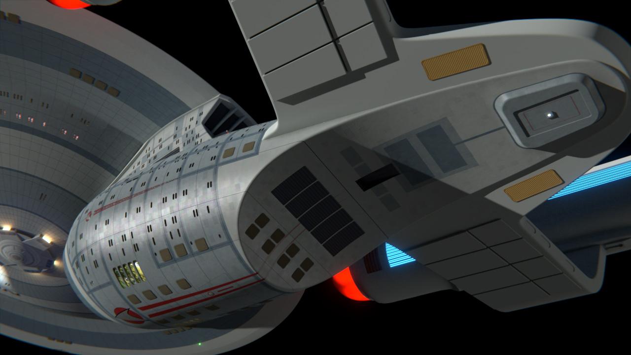
McC Your engineering hull is looking mighty fine from that angle.
I had no time whatsoever to work on it this weekend, sadly. Friday, my wife and I ended up deciding to go to a party that we hadn't originally planned to attend, Saturday we tried to recover from that and then had more people over for another round of chicanery, and then Sunday we spent the day shepherding a friend of ours through the David Tennant-to-Matt Smith transition (all four specials and then the first episode of series five!). Not sure what my free time looks like this week, but this coming weekend isn't currently booked solid, so hopefully as the week goes on, I'll have increasing amounts of time to devote to this!
On the topic of windows, I was thinking about abandoning my reference images (fan-created orthos and studio models alike) when it came to windows, and instead using (fan-created) deck layouts as a guide. The general arrangement of the windows would still be the same, but with the quantities and specific layout governed instead by the internal structure of the ship. This might also help inform a good placement for the aft torpedo tube.
Books: [ Ashes of Alour-Tan | Embers of Alour-Tan ] | Blender Tutorials | Blog
These are the "corrected" shield grid ring locations, based on comparing images of the studio model. I'll use these as my template for modeling my gridlines.
Books: [ Ashes of Alour-Tan | Embers of Alour-Tan ] | Blender Tutorials | Blog
Good luck!
Blah! This took far longer than it should have, largely because I got the fool idea in my head that trying to boolean shield grids was a smart idea. After 3-4 hours down that rabbit hole, I took a step back and did some poking around in the tutorial subforums here, where I realized that the inset poly group/extrude method would make way more sense and take way less time. Less than two hours later, we are here!
They aren't actually inset into the hull yet. Blender's Extrude Region tool seems hellbent on computing the average normal of the selected polygons and using that, while the Extrude Individual tool gives me the right normal vectors, but as the name implies extrudes each selected polygon individually, leaving me with a bunch of polygon "walls" that I don't want. Does anyone know a way to extrude a group of polygons, but along their local vertex/edge normals? Sort of a hybrid version of Extrude Region and Extrude Individual?
Books: [ Ashes of Alour-Tan | Embers of Alour-Tan ] | Blender Tutorials | Blog
In LightWave, I would use the Solid Drill or Stencil tools for hull detailing like this, which I've sorely missed in every other 3D package I've ever used. I think MAX has something equivalent to this, but I can't recall what it is. I know Maya does not.
It's not really useful to lament what your current 3D app doesn't have, unless you can actually do something about it (which, technically speaking, I probably could...if I had the time; I'm quite comfortable in Python). So far, this method is working alright, though.
One more update for tonight! I am very glad that this saucer is radial; means I only have to do 1/8th of the work (assuming I then mirrored the 8 radial wedges from one side to the other). If the saucer shape wasn't so regular, I'd have to do all the panels, and that would be incredibly tedious!
The grids are now properly inset (I chose a 15cm width and depth for them, which is an approximate compromise from the various measurements I gleaned from the studio model; ~5cm on the low end, ~30cm on the high end) and even microbeveled! Blender's Edit Mode Bevel is terribad (they're working on it!), but its Bevel modifier using Bevel Edge Weights is fantastic, so that's what I ended up using.
I actually made a small technical mistake on the lower grids, so I'll have to go in and re-do them. It's not actually something you're ever likely to see, but knowing it's there will bug me if I don't fix it. Fortunately, this method doesn't take very long to do, so that should be quick. I also flat-shaded the saucer for these renders, because the smoothing setup I was using looked all ripply. I'll go in and fix that next time, too.
And I should really model that bridge at some point...
Books: [ Ashes of Alour-Tan | Embers of Alour-Tan ] | Blender Tutorials | Blog
I use trueSpace, which is old and outdated, but it handles booleans better than some other software. In fact, booleans is the way to go on a lot of stuff with it. I've heard of other methods of doing lines in it, but the booleans is quick and easy and it doesn't suffer from a lot of the error problems that programs like Max and Blender have when using booleans. I have no idea if what I do in tS can be applied to Blender because I've only used booleans once in Blender and that was to cut a simple hole through something.
Thanks!
Books: [ Ashes of Alour-Tan | Embers of Alour-Tan ] | Blender Tutorials | Blog