Greetings!
Welcome to Scifi-Meshes.com! Click one of these buttons to join in on the fun.
Quick Links
Local TutorialModeling the Enterprise in Cinema 4D
Well, Scifieric kind of challenged me to do this, so here's my contribution to the general insanity that is modeling the USS Enterprise. I think many of these techniques could actually be used in other 3D programs (for instance, I did much of the following in 3ds max before my PC blew up), so take what you think you need and leave the rest. Hopefully it'll be helpful.
The Enterprise has, essentially, three basic shapesA…a saucer, rectangles (the warp drive pylons and the interconnecting dorsal) and cylinders (engineering section and the nacelles). The basic task of modeling these shapes is done by using vector-based shapes and manipulation of primitives, or A“lathingA†a shape. The actual task of modeling the Enterprise can be done fairly quickly, but the task of detailing the model is very time-intensive (and can lead to early male pattern baldness, marital stress, carpal tunnel syndrome, impotence, eyestrain, and other non-medical maladies).
Are you sure you still want to do this? Okay, then, letA’s proceed.
First, it is imperative that you familiarize yourself with your applicationA’s ability to import vector-based shapes. IA’m not talking about raster outlines done in Photoshop or Paint Shop ProA…IA’m talking about shapes done in Illustrator or any other program that uses vectors to describe shapes. These shapes are always much cleaner in appearance, can be resized almost infinitely, and (at least in Cinema 4D and 3ds max) can be used as the basis for extrusions, lathes, and other types of shapes. Some of you may say this is cheatingA…I say why go through the effort of using planes with GIF files pasted on them as the basis for drawing paths when those paths are already readily available? Save yourself some time and headache, man!
If you donA’t own Illustrator, see if your paint program will allow you to save out as an EPS (Encapsulated PostScript) file. If it will, then you can draw your paths in that program and export them out, then import them into your 3D app. If you canA’t do that, then youA’re back to drawing paths in your 3D program, using planes with the blueprints pasted on them, but thatA’s better than nothing. (The thread, A“How to build the Starship Enterprise in TrueSpace 3A†[http://www.scifi-meshes.com/forums/member-tutorials/727-how-build-starship-enterprise-truespace-3-a.html] has some excellent pointers on how to do that, much better than my humble self can describe.)
A good Open Source vector drawing program is Inkscape. It will allow you to do many of the same things as Illustrator. You'll still need the JPEGs to trace over, though.
Find a source for your blueprints or outlines. Two excellent sources are Alan SinclairA’s blueprints of the Enterprise (which can be found at Star Trek TOS 1701 Enterprise Gallery) and Charles CasimiroA’s set of blueprints (found at http://home.earthlink.net/~casimiro/blueprints.html). Both are very good, and you can use either to draw very good vector outlines. SinclairA’s blueprints also include fairly accurate measurements of each component, as well as measurements between components. These can be of immense help. Also, Sinclair has DXF files on his site (for use in AutoCad 3D) which can be imported into Illustrator and some 3D applications. Be warned, however, that these files, while very good, are very largeA…and there is quite a bit of work involved in being able to use these for your 3D work. If you can do it, itA’s probably easier to draw the paths in another application and import them into your 3D app.
Also, I mentioned above that primitives are used...there's a reason for that, and I personally think it's much easier than extruding polygons or stuff like that...even though it doesn't seem easier. But the method behind my madness will make itself apparent over time.
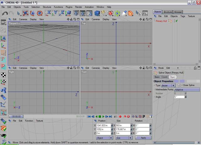
Okay, hereA’s where we get started. IA’m assuming youA’ve drawn your paths and youA’ve imported them into your application. In Cinema 4D, hereA’s what the screen will look like (click on the thumbnail to enlarge):
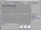
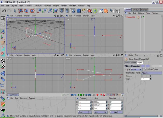
Oh, you donA’t see it yet? ThatA’s because, for some reason, C4D doesnA’t paste the object directly in the center (or at 0,0,0). Notice your X, Y and Z positions at the lower center of the screen. Each of these should read zero. So go into each field, highlight the numbers, then replace them with zero. Now hereA’s what youA’ve got:
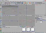
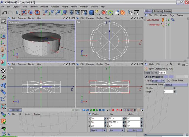
Okay, thatA’s better. But notice your pathA…the axes are in the center of the path. That may not seem like a big problem, but when you try to lathe it hereA’s what happens:
Hmm, thatA’s not what we want. Since the lathe function in most programs uses the Y axis (up/down) as its rotation point, we need to move the Y axis. In C4D, hereA’s how you do it.
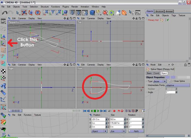
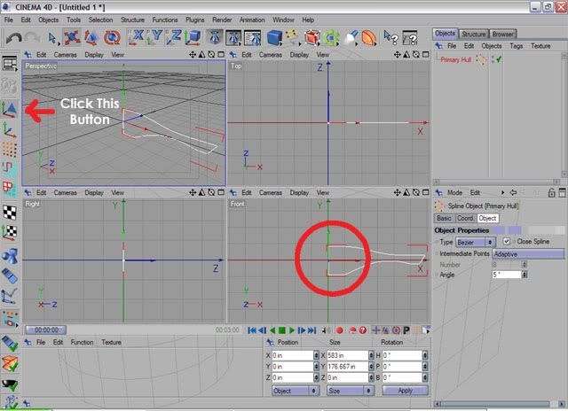
First, note how big your path is in the X axis. In this case, itA’s 583 inches. (Yes, thatA’s way too big, but ignore it for nowA…just look at the numbers.) The path is centered on the X axis. In order to lathe properly around the Y axis, we need to align the Y along the left edge of the path (what would be the A“centerA†of the shape). Note the icons along the left edge of the screen. The second icon (directly below the one thatA’s selected) allows you to align the A“axisA†without moving the path. Click that button, then in the X position field, type in half of the 583 thatA’s in the X size field. (That would be 291.5.) Put a minus in front of the number. This allows you to move the axis to the extreme left of the path.
Okay, that moves our axis where it needs to be, but our path is still centered on the X/Y axis. ThatA’s easy. Click on the button above the axis position button, and in the X position field, type 0. That moves everything back to the right.

Next: Lathing the saucer
The Enterprise has, essentially, three basic shapesA…a saucer, rectangles (the warp drive pylons and the interconnecting dorsal) and cylinders (engineering section and the nacelles). The basic task of modeling these shapes is done by using vector-based shapes and manipulation of primitives, or A“lathingA†a shape. The actual task of modeling the Enterprise can be done fairly quickly, but the task of detailing the model is very time-intensive (and can lead to early male pattern baldness, marital stress, carpal tunnel syndrome, impotence, eyestrain, and other non-medical maladies).
Are you sure you still want to do this? Okay, then, letA’s proceed.
First, it is imperative that you familiarize yourself with your applicationA’s ability to import vector-based shapes. IA’m not talking about raster outlines done in Photoshop or Paint Shop ProA…IA’m talking about shapes done in Illustrator or any other program that uses vectors to describe shapes. These shapes are always much cleaner in appearance, can be resized almost infinitely, and (at least in Cinema 4D and 3ds max) can be used as the basis for extrusions, lathes, and other types of shapes. Some of you may say this is cheatingA…I say why go through the effort of using planes with GIF files pasted on them as the basis for drawing paths when those paths are already readily available? Save yourself some time and headache, man!
If you donA’t own Illustrator, see if your paint program will allow you to save out as an EPS (Encapsulated PostScript) file. If it will, then you can draw your paths in that program and export them out, then import them into your 3D app. If you canA’t do that, then youA’re back to drawing paths in your 3D program, using planes with the blueprints pasted on them, but thatA’s better than nothing. (The thread, A“How to build the Starship Enterprise in TrueSpace 3A†[http://www.scifi-meshes.com/forums/member-tutorials/727-how-build-starship-enterprise-truespace-3-a.html] has some excellent pointers on how to do that, much better than my humble self can describe.)
A good Open Source vector drawing program is Inkscape. It will allow you to do many of the same things as Illustrator. You'll still need the JPEGs to trace over, though.
Find a source for your blueprints or outlines. Two excellent sources are Alan SinclairA’s blueprints of the Enterprise (which can be found at Star Trek TOS 1701 Enterprise Gallery) and Charles CasimiroA’s set of blueprints (found at http://home.earthlink.net/~casimiro/blueprints.html). Both are very good, and you can use either to draw very good vector outlines. SinclairA’s blueprints also include fairly accurate measurements of each component, as well as measurements between components. These can be of immense help. Also, Sinclair has DXF files on his site (for use in AutoCad 3D) which can be imported into Illustrator and some 3D applications. Be warned, however, that these files, while very good, are very largeA…and there is quite a bit of work involved in being able to use these for your 3D work. If you can do it, itA’s probably easier to draw the paths in another application and import them into your 3D app.
Also, I mentioned above that primitives are used...there's a reason for that, and I personally think it's much easier than extruding polygons or stuff like that...even though it doesn't seem easier. But the method behind my madness will make itself apparent over time.
Okay, hereA’s where we get started. IA’m assuming youA’ve drawn your paths and youA’ve imported them into your application. In Cinema 4D, hereA’s what the screen will look like (click on the thumbnail to enlarge):
Oh, you donA’t see it yet? ThatA’s because, for some reason, C4D doesnA’t paste the object directly in the center (or at 0,0,0). Notice your X, Y and Z positions at the lower center of the screen. Each of these should read zero. So go into each field, highlight the numbers, then replace them with zero. Now hereA’s what youA’ve got:
Okay, thatA’s better. But notice your pathA…the axes are in the center of the path. That may not seem like a big problem, but when you try to lathe it hereA’s what happens:
Hmm, thatA’s not what we want. Since the lathe function in most programs uses the Y axis (up/down) as its rotation point, we need to move the Y axis. In C4D, hereA’s how you do it.
First, note how big your path is in the X axis. In this case, itA’s 583 inches. (Yes, thatA’s way too big, but ignore it for nowA…just look at the numbers.) The path is centered on the X axis. In order to lathe properly around the Y axis, we need to align the Y along the left edge of the path (what would be the A“centerA†of the shape). Note the icons along the left edge of the screen. The second icon (directly below the one thatA’s selected) allows you to align the A“axisA†without moving the path. Click that button, then in the X position field, type in half of the 583 thatA’s in the X size field. (That would be 291.5.) Put a minus in front of the number. This allows you to move the axis to the extreme left of the path.
Okay, that moves our axis where it needs to be, but our path is still centered on the X/Y axis. ThatA’s easy. Click on the button above the axis position button, and in the X position field, type 0. That moves everything back to the right.
Next: Lathing the saucer
Post edited by dan1701a on
Additional credits
- Icons from Font-Awesome
- Additional icons by Mickael Bonfill
- Banner background from Toptal Subtle Patterns
© Scifi-Meshes.com 2001-2024
Posts
Okay, now you can lathe the outline. In C4D, click on the button up top that has an orange box with a cage around it, and in the resulting window choose the button that looks like a vase. Obviously, different 3D apps will have different methods for lathing an object, but weAâre sticking with C4D right now.
And here's what that little sub-menu looks like:
Your object window will now look like this:
But your shape hasnAât changed! WhatAâs up? Well, C4D (and many other 3D apps) use a hierarchical object methodAâ¦in other words, you have a top-level effect (parent) and other effects, paths, shapes, etc. (children) that the effect acts upon. To make the lathe modifier affect the path, click on the path item in the object window and drag it on top of the Lathe NURBS effect (not above it, but directly on top). This will AânestAâ the path inside the Lathe NURBS effect, and now your screen looks like this:
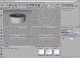
Well, thatAâs certainly looking much better! However, you can see it has many straight edgesAâ¦it approximates a circle, but itAâs not smooth. Go back to you Lathe NURBS effect and change the subdivision modifier to something smoother (a minimum of 64, maximum of whatever your computer will handle):
Once thatAâs done, itAâs looking more like a primary hull.
Now would be a good time to save your work.
Next: Darned numbers!
I need to back up a little bit. When you draw your path for the primary hull (or import it from Illustrator), consider that there are three concentric rings on the lower side. Those can either be modeled in (by creating AânotchesAâ in the path in those locations) or created by using a bump map, which will be touched on later. Bump mapping is easier, but not as clean. Consider which way you want to do the rings when you draw your paths.
Okay, now we have a primary hull. Here is where we might want to start aligning things. Alan SinclairAâs drawings contain measurements for each component of the ship, as well as measurements between things like the nacelles, center points, etc. The documents state that the primary hull is 59.25 inches in diameter.
Oops.
Our path is 583 inches wide (and since our path was only half the total saucer, that means our actual saucer is 1166 inches, or just over 91 feet, in diameter!), so we have to make the path smaller.
If the diameter in the diagrams is 59.25 inches, then the radius would be half that, or 29.125. However, if you type that into your X size field, itAâll change that parameter but leave the others untouchedAâ¦and that will make your path look goofy. So what to do?
Well, if you scale it instead, you can get it to the right size and keep it looking the same. Under the AâsizeAâ fields, there is a drop-down menu. Currently it says Aâsize,Aâ but it has two other items, Aâsize+Aâ (which I still havenAât figured out what it does) and Aâscale.Aâ Click on the double arrows to the right of AâsizeAâ and choose AâscaleAâ from the drop down menu. This changes all the values in the fields to 1.
But what scale is 29.125 compared to 583? HereAâs where you have to do some math. In order to find this value, divide 29.125 by 583. The answer you come up with is 0.049957118353344768439108061749571, and believe it or not you can copy that number from WindowsAâ Calculator and paste it into each of the scale fields, but when you round up to the nearest 100th you come up with 0.05. Type 0.05 in each one of the scale fields and click Aâapply.Aâ HereAâs what your screen looks like, if you did it right:
Notice the value in the X size field is now 29.15 inches. Well, thatAâs probably close enough. That would be considered the radius of the primary hull, making the diameter 59.3 (not much off from 59.25). For our purposes, thatAâs probably close enough.
(Note: if you wanted to get more accurate, paste the actual number shown above into the scale fields, and itAâll make your hull measurements absolutely accurate.)
Now we need to move the primary hull to where it needs to be. For all my measurements, IAâm using the forward end of the secondary hull as my AâzeroAâ point (Aâforward endAâ meaning the edge of the amplification rings, or what I call the end cap). HereAâs where we get into some more calculations. The center point of the primary hull is 17.5 inches forward of the front edge of the secondary hull. But how far above the secondary hull does it go? Unfortunately, the diagrams donAât go into that much detail, but IAâve made some calculations that should help. Without going into too much detail, the top surface of the saucer sits 18.01Aâ above the center line of the engineering hull. In other words, imagine a rectangle that is 18.01 inches tall and 17.5 inches wide. The top edge of the primary hull (the flat part, not the very top) aligns with the top of the rectangle. The center of the primary hull aligns with the left edge of the rectangle. In other words:
DONAâT move the Primary Hull in the Z axis at all Aâ leave that number at zero.
Next: The Secondary Hull
Okay, that was the easy part.
Now that thatAâs said, letAâs start on the secondary hull. ItAâs basically a cylinder thatAâs somewhat tapered near the aft end, so thatAâs what weAâre going to start with. YouAâll need to create a cylinder that is 44.75 inches long and 13.4 inches in diameter. Align it along the X axis (or create it and rotate it 90 degrees along the X axis), so that it lies on its side.
Place it so its forward (or far left, in this case) end is 4.25 inches to the right of the X-Y origin (X=4.25). Give it about eight height segments, and at least 36 segments around the circumference (more will make it smoother). And make it editable. HereAâs how it should look now:
ThereAâs our cylinder, but now we need to AâshapeAâ it to look like the secondary hull. HereAâs where you need another path. Either lift the path from Alan SinclairAâs DWG files (converted to AI) or draw it using your favorite vector drawing program and SinclairAâs or CasimiroAâs JPG blueprints. Remember to draw the path as a vector-based file (EPS) as opposed to a raster-based picture file (BMP, GIF, JPG, etc.) Alternatively, you could use a properly-shaped plane with the GIF of the secondary hull outline textured onto it, and it would probably work, but possibly not as well. There are nearly as many methods out there as there are 3D modelers, so find your own method. HereAâs mine.
Import the path into C4D. Again, youAâll find itAâs about 400 times bigger than it needs to be. Resize the path to be 44.75 inches long (X) and 13.4 inches tall (Y). Fortunately, you donAât have to worry about the Z axis yet. Center the path (X, Y, Z should be 0), then move the pathAâs axis to the far left edge of the path, then move the path to where it is overlapped by the cylinder. HereAâs basically what it will look like:
(I turned off the cylinder for clarity.)
If you havenAât already made your cylinder editable, do so now. YouAâll need to be able to move points around to get your cylinder close to the shape of the secondary hull. HereAâs what your cylinder will look like once you enable the points for editing:
HereAâs where things get interesting. You now need to lasso each AâcircleAâ of dots and scale them to match the outline. Use a lasso or rectangular marquee tool rather than a direct selection tool, and (at least in C4D) make sure you turn OFF AâOnly Select Visible Elements.Aâ This way you will select all the points, not just the ones facing you. HereAâs what that looks like:
Now use your scale tool to scale that AâcircleAâ to match the outline. There are no reliable cross-section measurements available for the secondary hull, so youAâll have to do the best you can by eyeballing it. You can probably get pretty close, though. Note, too, that you may have to move some of the dots further forward, backward, up, or down, depending on which part of the outline youAâre trying to match. The most critical parts are in the front, because after the widest part of the outline it all pretty much slopes evenly toward the back. In fact, if it turns out you have too many points, you may be able to delete some (hopefully without deleting sections of the cylinder; if you do that youAâll have to start over. Remember, CTRL-Z is your friend.
That was easy, wasnAât it?
Next: Cutting and Chopping
We still have a couple of more things to do to this cylinder before it more closely resembles the secondary hull, though. First, you need to clone the secondary hull path, because you’ll be using these to create Boolean cutouts. Simply copy the path and paste it a couple of times, then isolate one of them for editing. Change to points mode in your app (in C4D, click the icon that looks like an array of dots), then begin moving dots around until the cutout on the bottom rear looks like this:
Again, the cylinder has been removed for clarity. Now, use your extrude tool to extrude this shape in the Z direction (towards/away from you), enough to extend beyond the sides of the cylinder.
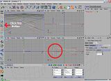
Now is where we get to have some fun. On the C4D button bar is a button that looks like a blue dot with six green boxes surrounding it, kind of like a strange looking flower. Click that button and you get a submenu with choices that look like this:
The red circle is around the Boolean function. Yours may be similar, depending on your 3D app, but all Boolean functions work the same. It takes two items and subtracts the intersection point, as well as all of the first item. I’d go into a long, drawn-out explanation, but you guys have done this before (hopefully). Just make sure your main cylinder is the "A" object and the cutout is the "B" object. You'll be doing an "A subtract B" operation. At any rate, here is what this Boolean function looks like:
Well, now it’s beginning to look more like a secondary hull, isn’t it? Here's where using a primitive instead of "lathing" or "skinning" a hull becomes an advantage. Note that, when we cut out the fantail, it left a solid surface as opposed to an empty hole. This way you don't have to add any polygons or stitch any points together. But there are still quite a few things to be done. The hangar deck, for instance. Well, that’s easy. First, rename your first Boole to something else, like “Engineering Hull.” Next, take one of your other secondary hull outlines and do the same thing with it that you did with the fantail.
(Side note: I had to make the secondary hull editable because I wound up with a stray point that I had to edit out.)
It’s starting to look a little more like a starship. We’ll leave the secondary hull for now and proceed to the nacelles. The same technique applies here as did the secondary hull. Get the outline of the nacelle first, and resize it. The length should be 63.67 inches and the height should be 7.65 inches. Place the nacelle at these coordinates: X=18.79, Y=21.475, Z=19.5. This should give you the basic layout of the starship. Now, make a cylinder 63.67 inches long and 7.65 inches in diameter, then place it at the same coordinates at the outline. Make the cylinder editable, then manipulate the points the same way you did the secondary hull. Note: give this cylinder 21 height segments. When you're done with that, duplicate that cylinder, then change the Z coordinate to -19.5. This is the final result:
Those are probably the major assemblies. The dorsal, pylons, and the amp rings for the secondary hull still need to be created, and the smaller structures like the bridge, B-C deck, lower sensor array, impulse engines, and the components that go on the nacelles. But those four structures above comprise the basic shape of the U. S. S. Enterprise.
Coming soon: How to make those nit-noid structures, plus other things.
Note: if you want really detailed measurements that aren't on Alan's latest blueprints, go here: [url=http://bruts_3.tripod.com/public_resource_enterprise/asinclair_enterprise/index.html]PUBLIC RESOURCE ENTERPRISE: Alan Sinclair's Enterprise[/url]. The page itself might be old, but the measurements are accurate. It's an invaluable help, and the picture files can be saved (although they're not the latest revision). Great resource!
Well, it was your idea. :thumb:
Actually, I never sat down and actually thought about how I did it before, but doing this tutorial allowed me to cut out a bunch of the intermediate steps I had taken that slowed down the process. I actually wrote that part of the tutorial over the weekend.
Now, the smaller items will take a little longer, but looking at all the great tutorials on this forum (including yours in tS 3) has given me some ideas..........
Maybe once we have completed tutorials for both the TOS and the TMP version, in the major apps, we can combine them all into a single uber-PDF. I have a feeling it would be very popular.
I have a feeling you are correct!
Seriously, it seems like many of the techniques you use to model the ship are the same no matter what app you use (with the possible exception of Blender). And most of the terms are the same between apps (heck, even Moray has an "extrude" function). Somebody should be able to put a generic tutorial together with cross-refs between apps, so that when one calls for a "lathe" and another calls for a "spin" everybody will know what it's talking about. Or maybe someone could simply gather all the different terms between apps and cross-ref them as a start.
And no, I'm not volunteering! :devil:
LOL!
I thought Jedilaw was volunteering. He did say "we" should make the super tut... :shiner:
:runs:
*Teach you to hide my droids... sniff.
I'm having a hard enough time with the B/C deck...an uber-tutorial would pretty much wreck my marriage!
And hopefully I'll learn an easier way to do it!
That's it exactly. Most of us here already have a fair to midling grasp of the programs we use. The real help of tutorials is to get us to think of a problem a different way. For example, for my secondary hull, I use a lathed spline, it never even accurred to me to use a cylinder and scale the sections down. The bitch of it is, both acheive exactly the same thing.
Until I learned how to use the "close polygon" function of C4D, the reason I used the cylinder is, when I Boole'd the fantail, it left me with a solid surface and few, if any, mesh errors. Doing a lathe, I discovered, gave me mesh errors when I Boole'd the fantail.
But some of the techniques ScifiEric uses tend to turn the light bulb on for me, and that's what I hope to do for others...as soon as I make sure they work for me, and they're repeatable. :thumb:
Actually, I screwed up. I tried a new technique that allowed me (or I thought it allowed me) to get rid of some of my booleans and retain my shapes. Unfortunately, it didn't work the way I hoped it would, so I'm redoing the secondary hull.
Also, I've been playing with some of my techniques in Blender, so it's taken me a little longer to hit the C4D tutorial. (Plus, Tallguy, if you're reading this - great job on your 1701 mesh! How'd you do it? I think a tutorial is in order...)
I hope to reattack it soon, so meanwhile, please stay tuned! :thumb:
And yeah, Tallguy's Enterprise is spectacular!
I would suggest that anyone who wants to get to the meat of Cinema jump right in and do the Rubber Duck Race tutorial included on the CD. You won't get all the concepts immediately, but it allows you to touch all parts of program (modeling, textures, animation, etc.) and get a rudimentary understanding of the interface and how it is arranged.
I would just like to compliment you guys on an outstanding site, BTW. Hope I can contribute when I am a little less green.
Steve
I've also been following Four Mad Men's Big E over at hobbytalk.com. He's doing his in Blender as well, so that is kind of encouraging me in that direction.
I like Cinema 4D a lot (I also like 3ds max), but I've discovered that Blender has some advantages (for instance, the megabool function), and although it also has some quirks (the interface, for instance), I've decided to go Blender...meaning that my C4D tutorial will probably never be finished, at least in that application.
However, the techniques I used, I believe, are applicable for just about any 3D package (with the possible exception of Wings3D), so I may be able to continue it in Blender later on.
But I've asked 4MM (at the Hobby Talk forums) to share some techniques, and once I learn a little more about Blender, I will probably start back up. Although I'm not sure I can match either 4MM's or Tallguy's expertise, but maybe my small contribution will be valuable to someone.
Oh, yeah, did I mention I didn't want to break the bank buying 3D apps? And that Blender is free? That was another consideration.
As Dan suggested, I used the Alan Sinclair blueprints as a spline. I opened them in Illustrator, took out the parts I needed and saved as an Illustrator 8 eps file, however, for some reason, C4D would not open it (I have version 9.6; there is no import command; it opens what it can open) so I went in again, saved as an Illo 8 file, and this time success. However, Mr. Sinclair had used path segments to create the contours for his blueprints, and not only that, in order to get the shapes completely right, he twisted the paths. The bottom line is that when opened in C4D this resulted in a parent object (primary_half) with something like 8 child paths. This would not lathe as one solid object. Needless to say the twisted paths would create uneccessary extra polygons if it could be lathed.
I went back to Illo and I joined and corrected each segment and removed all unneeded points. I also added the "dugouts" for the three circles in the bulge on the bottom. Saved again and opened in C4D. Success. I went ahead and lathed with 128 segments. I also went ahead and did the same procedure on the lower sensor array, just to see if I could accomplish it. It also had to be "fixed" in Illo before saving. I then Merged that into the first scene, placed, lathed and then I grouped both objects.
Dan is right, using the plans gives you a better final result, especially on the sensor dish. Please also note that if you use the DXF version, and are using SI (metric) as your measurement system in your modeller, your spline will open up at the right size. As Dan pointed out, it will not open at the origin, but moving it there is not a problem. Scaling should not be a problem if you want to do so.
I have provided pics of the work. I brought in a floor object, shaded the hull and the floor the same nutural beige, used the sky plugin as a quick lightdome and placed one spot light to soften the shadows.
I am going to improve the spline even more as I am not too happy with the results for the bottom of the hull. I am going to use Dan's advice on the secondary and nacelles, but I want to finish the primary first, so I am going to use scifieric's procedure for the upper decks and impulse engines. I will post them as soon as I can.
Top:
Bottom with sensor array:
Steve :idea:
I noticed what you mentioned about Alan's paths being looped...I don't know what the deal was, unless he did it in a different version of AutoCad that interpreted curve nodes differently. It took me so long to try to clean it up, I just found his GIF files and redrew the contour over that. I don't think his nacelles or secondary hull have that problem, though.
My main issue with C4D was cost. I was able to get version 9 from a friend, but I really needed to upgrade, and I didn't really want to pay hundreds of dollars to do it. Blender is free, and although the interface is really quirky, after a while you get used to it. There are a lot more keyboard shortcuts used, but when you get good at it you can move pretty fast (as I'm sure Tallguy and FourMadMen can attest). Right now my main issue with Blender is the fact that you have to convert your curve or path to a mesh before you can lathe, but I figured out you don't need a closed curve to do that (like you do in C4D). The other main issue I have right now is memory and processor (try doing 3D on a 1.8gHz Celeron with 512mb RAM, 64 of which is shared video memory, and a 30gb 4200 rpm hard drive -- it's a frustrating experience). I'm not advocating one package over another -- whatever works best for you is what you should use. I've used everything from Wings3D to Alias|Wavefront (the old version of what is now Maya), and I've found that free is often a good way to go. :thumb: Plus I'm an open source advocate (or, as they say, free speech as well as free beer) and the more we support the open source software movement the better quality software we get for all platforms. Maybe someday I'll learn to code, too, but for right now 3D is about all I can handle. That and my job.
Dorsal:
Ventral:
You were right about the rings Dan, I confused the outer ring with the top lip of the primary hull (Mr. Sinclair does not have a hidden line for that, so I measured in Illo and it worked great). I also got rid of even more points and followed the contour of the hull more closely. Some of my "improved" lines were off by a few millimetres. Please note there is no "Flat spot" on the dorsal nor extra fillet on the ventral.
I understand where you are coming from costwise. Because I am a student, I managed to get C4D 9.5 (with BodyPaint, Clothilde, and some plug-ins) for several hundred less than normal. I have also tried Lightwave, Maya LE and blender which all had me run screaming into the night (have I explained about my avatar... ?) The reason I finally went for C4D was I actually modelled something in it besides a cube. Okay, I did a sandcastle tute in LW, but it was problematic.The C4D 9.6 updater was free, and my current serial worked fine. I ran through the tute on the CD (the rubber duck race) which goes through modeling and animating a whole scene using XPresso to rig the animation. I went through it quickly, but as I said in my first post here, I have now at least done something and touched something in the entire program.
Anyway, on to the upper decks, bridge and details.
Steve
Something looks very, very wrong on that last picture. You shouldn't have a seam at the apex of the scalloped-out part of the hull curvature.