Greetings!
Welcome to Scifi-Meshes.com! Click one of these buttons to join in on the fun.
Quick Links
3DWhat Have I Been Up To? Learning Blender!
 JES392
Posts: 195Member
JES392
Posts: 195Member


For the past month (or so). Still learning the software though.
For my first attempt, I decided to try this old design: the Paladin-class Destroyer/Scout.
Have I lost my mind, giving the Sovereign class a go? Probably...
 .
.
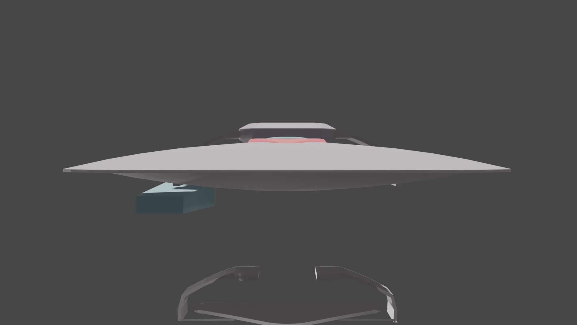
And then I went crazy, and decided to give a go at the Galaxy Class...

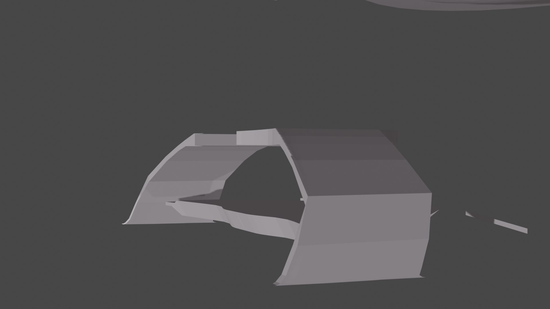
The aft of the underneath of the ship. I started on this by itself, independent of the rest of the ship, but found that there were too many vertexes to attempt to attach it to the rest of the ship! Oops! At the very least, I know what I want the bottom aft of the ship to look for.
The pod pylons were one of the first objects that I tested applying subdivision to. It's a shame that for some reason, the subdivision modifier doesn't appear in the render, and the object is too complicated to integrate with the rest of the ship!
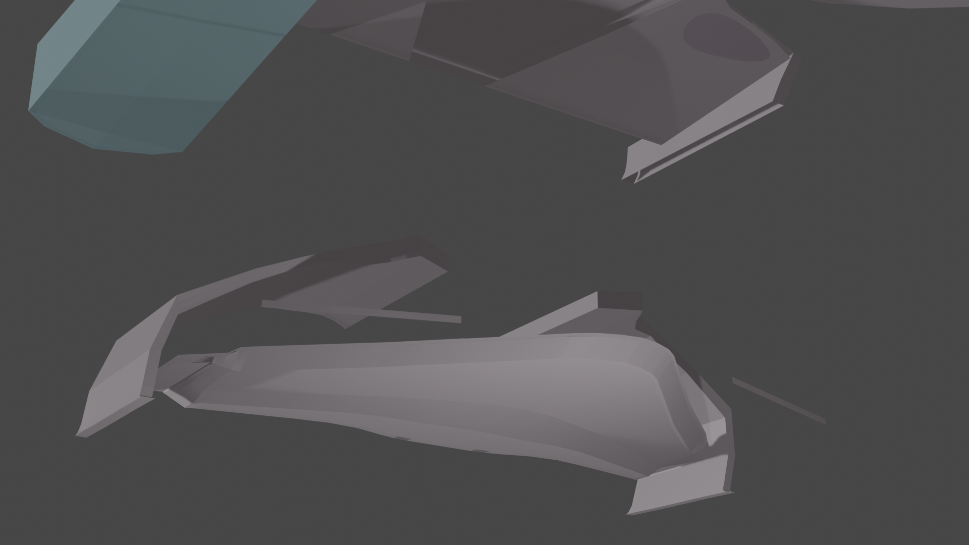
This was supposed to be part of the ventral hull, only for me to find that integrating it with the rest of the ship vertex by vertex was too complicated! I'm starting over, with plans to maybe eventually put a nav deflector here.
It took multiple attempts to get to this point, during which I learned that it is important to make sure that I have everything in place BEFORE subdividing (in which case, there are so many vertices, it becomes too complex to move them with any sort of accuracy).
Eventually, I found myself moving too slow, afraid of ruining something and having to start over again! So I found this detailed X-Wing tutorial, and have been plugging away at it since early this week.
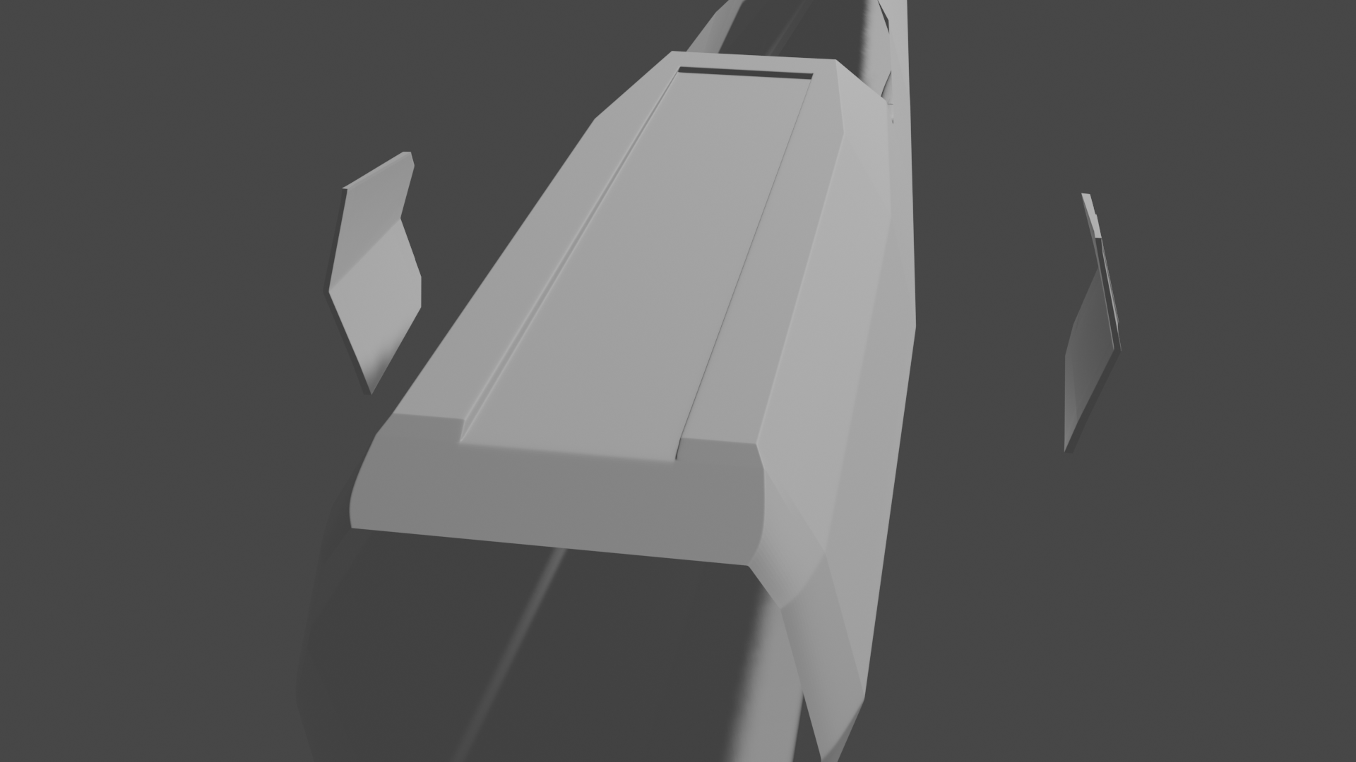
I'm especially proud of how I got the shape of the aft dorsal to come out, and my first torpedo tube isn't too bad looking either.
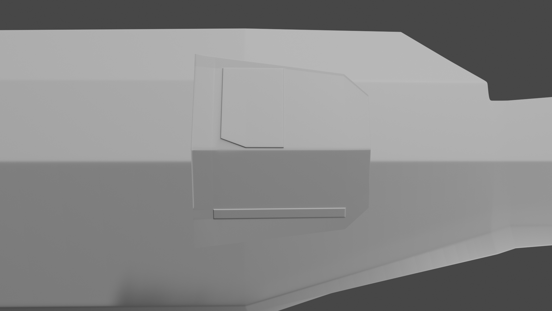
I am proud of how the panel came out, but have also learned to make sure that any panels that I work on lie flush with the parent surface BEFORE beginning subdividing! I'll likely have to just start over!
Also, how do you get the subdivision surface to appear in renders? I have them on, but it disappears during my renders for the Paladin?
For my first attempt, I decided to try this old design: the Paladin-class Destroyer/Scout.
Have I lost my mind, giving the Sovereign class a go? Probably...
.And then I went crazy, and decided to give a go at the Galaxy Class...
The aft of the underneath of the ship. I started on this by itself, independent of the rest of the ship, but found that there were too many vertexes to attempt to attach it to the rest of the ship! Oops! At the very least, I know what I want the bottom aft of the ship to look for.
The pod pylons were one of the first objects that I tested applying subdivision to. It's a shame that for some reason, the subdivision modifier doesn't appear in the render, and the object is too complicated to integrate with the rest of the ship!
This was supposed to be part of the ventral hull, only for me to find that integrating it with the rest of the ship vertex by vertex was too complicated! I'm starting over, with plans to maybe eventually put a nav deflector here.
It took multiple attempts to get to this point, during which I learned that it is important to make sure that I have everything in place BEFORE subdividing (in which case, there are so many vertices, it becomes too complex to move them with any sort of accuracy).
Eventually, I found myself moving too slow, afraid of ruining something and having to start over again! So I found this detailed X-Wing tutorial, and have been plugging away at it since early this week.
I'm especially proud of how I got the shape of the aft dorsal to come out, and my first torpedo tube isn't too bad looking either.
I am proud of how the panel came out, but have also learned to make sure that any panels that I work on lie flush with the parent surface BEFORE beginning subdividing! I'll likely have to just start over!
Also, how do you get the subdivision surface to appear in renders? I have them on, but it disappears during my renders for the Paladin?
Post edited by JES on


Additional credits
- Icons from Font-Awesome
- Additional icons by Mickael Bonfill
- Banner background from Toptal Subtle Patterns
© Scifi-Meshes.com 2001-2024
Posts
As for subdivision, you have two numbers in the interface:
The top number is how much the Sub-D will be visible in the 3D viewport, whereas the bottom number is how much it will be visible in the render. If you have either number at 1, you won't see any Sub-D. So, whatever you set the bottom number to is how much Sub-D you'll get in the render.
I have to say, this is pretty unique to Blender, as far a different levels for viewport and render, at least among the 3 different programs I've used in the past 20+ years.
Thank you, but the only reason I've gotten this far is on tutorials and lots of searches. And copious amounts of cursing. I would recommend giving it another go. You should be able to find a tutorial for something you'd like to build.
Keep it up. The only way to learn is to keep plugging away at it.
I've learned that for some strange reason, the subdivision mod disappears in the Paladin file unless I click apply. Probably a stupid glitch. Hopefully, it will remain unique to that file only.
I would also add that loop and vertex slide is one of my best friends. Initially, I thought I just had to keep adding loop cuts until I got the loop where I wanted it (and then had to go back and delete the extras I didn't!)
Ever since I've discovered the slide tools, I swear that my work efficiency has doubled! I am still cautious about adding them too soon though. I find the less vertices there are to work with, the easier to triangulate the proportions.
This is great advice for users. Of any skill level. Can't count the number of times I wished I saved earlier before starting a new step.
Doing this is probably above my skill levels, but I was obsessing over it too much. I have special plans for this!
I'm sure most everyone here will agree on that one.
I'm using 3.4.
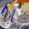
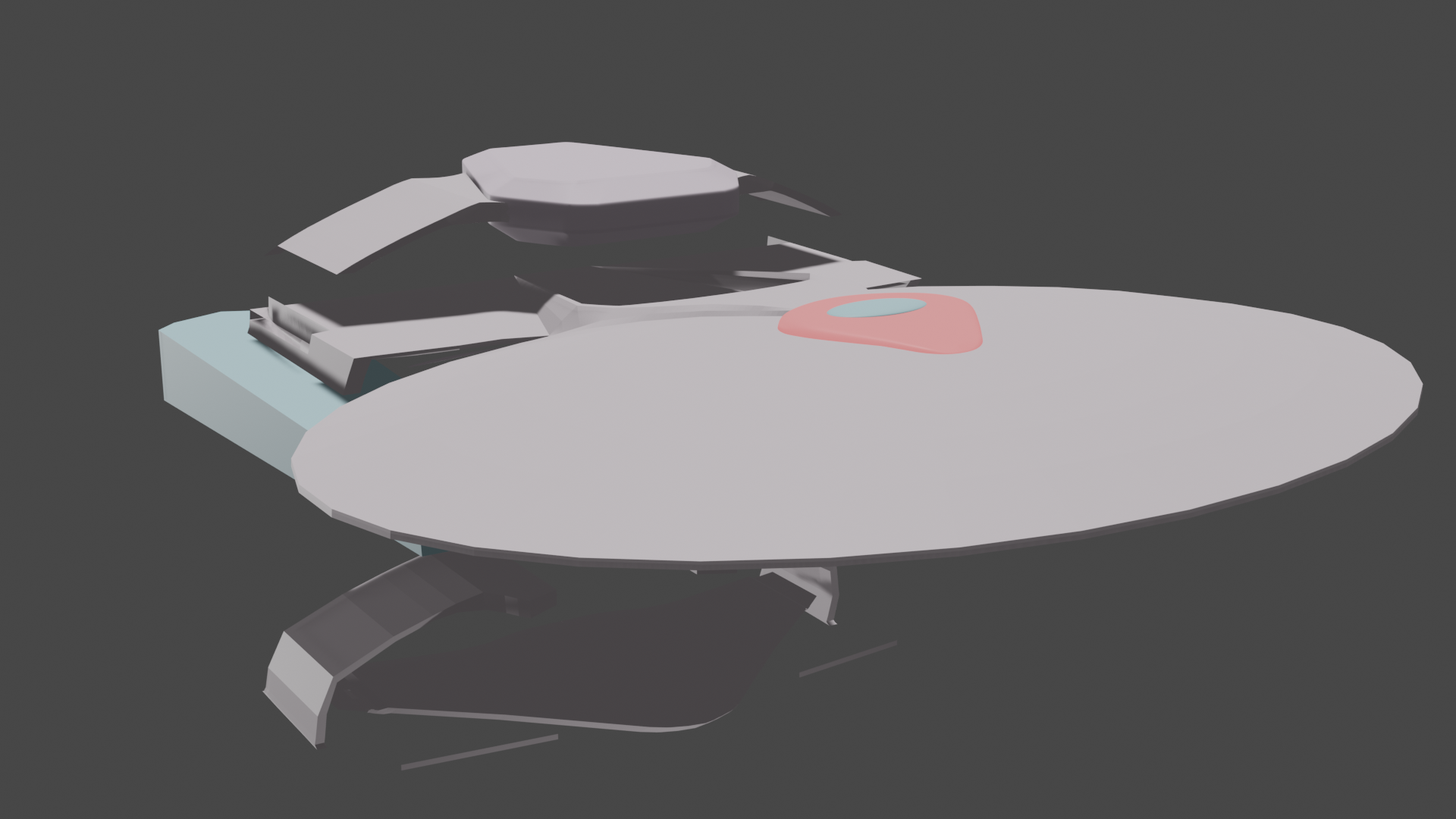
I managed to knock out the basic shape of not just the saucer section, but refine the engineering hull a little too. Next up is the next, which is going to involve complex extrusions. I'm just posting my progress before bed.
I also positioned the vertex grid of the engineering hull, with the intent of loop cutting and extruding in the deflector grid later. Since the triangle count is already at over a million, there might also be some vertex culling in the near future, specifically those inhabiting the saucer section.
Finally, I plan on saving this into two files, since I've been planning on making a variant. I just have to finish off the basic shape of the neck, and that's where they'll diverge.
Could be. But for the moment, it isn't causing a debilitating problem, so I'm keeping it as is for now.
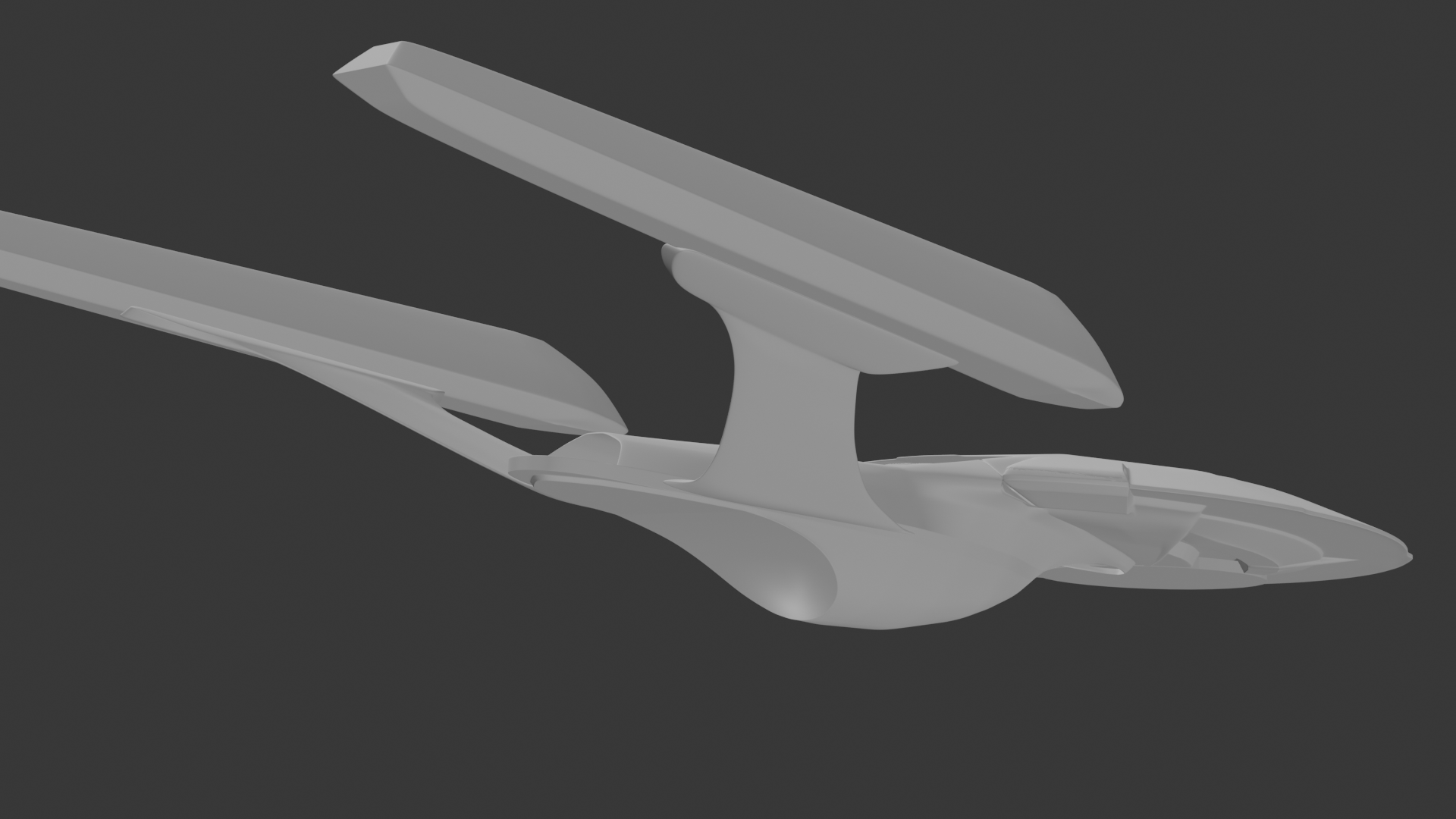
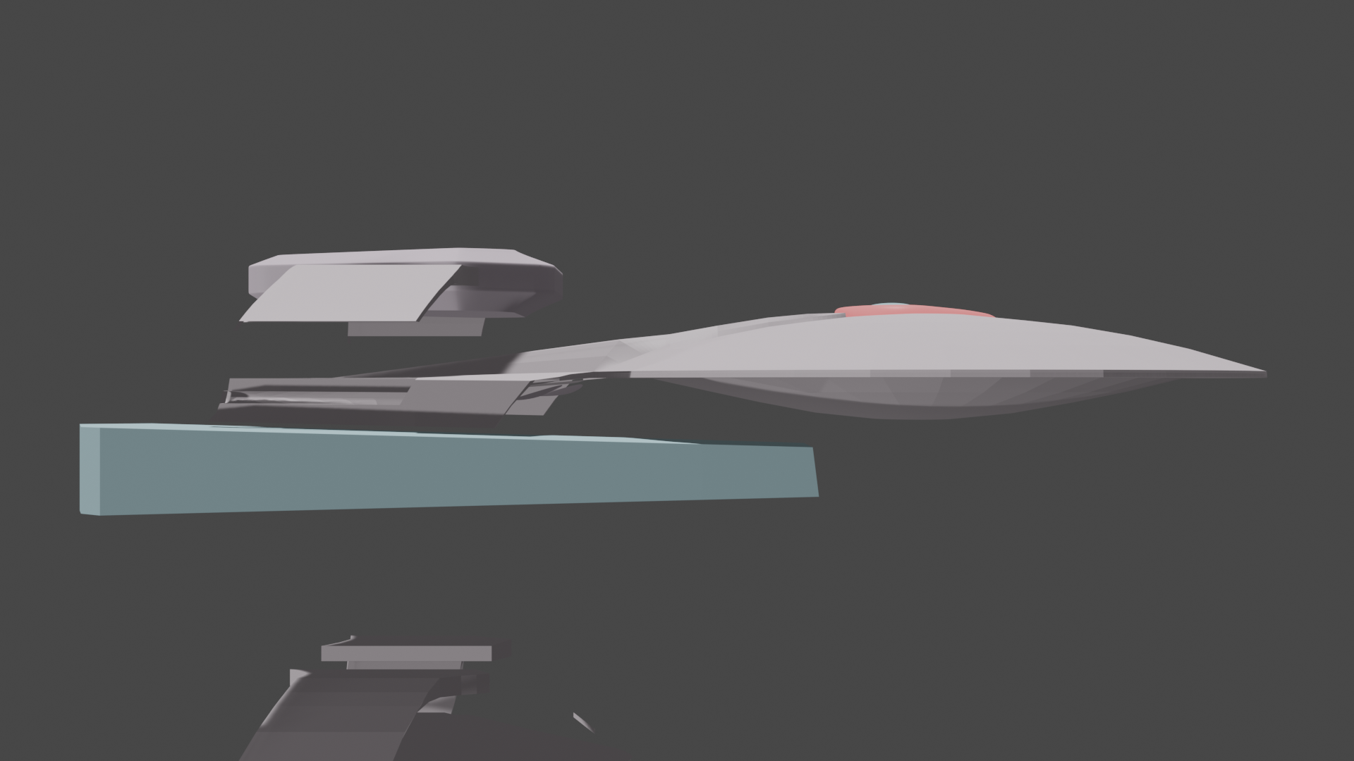
Moving on to the neck, which I managed to get blocked out for the most part. Still in need of refinement, but, hey, it's a start! Probably not going to have any more time to work on it tonight (stupid laundry, not folding itself!), so I'm posting this here now.
Even though very intricate, due to being a quite complex curve, this has been also one of my favorite parts to work on.
Interestingly enough, the thickest part of the neck isn't towards the back, like I've always thought, but more towards the middle, behind the torpedo launcher (the thinnest part of the neck), but ahead of the secondary impulse deck and neck flare. Maybe I need to make a render of the neck from directly aft to show what I'm talking about.
The Galaxy class really is an intricate design, which is why I've been holding off on detailing her just get. And yet, I've also been sliding vertices in preparation for the deflector grids when she's finally perfect, since that will be much harder to fix if everything else isn't in place yet.
Nor would I. But I love the fact that you're going big on your first model.
I decided to start on the nacelle, only to have to delete it because the subdivision wasn't doing what I needed it to do. It was flattening out instead of curving, and there was just too many different loop cuts to deal with, to the point it was just faster to start over. I don't know if this was because I extruded parts inwards to later make way for the bussards, warp grills, and emergency flush vents.
About the only good thing was that this happened before I started working on the deflector grid.
Just in case things get bad, if I downgraded it to an older version, would my (current) files still be completely compatible?
Good question. Theoretically, I think it would work since Blender doesn't change their file format. And, you're presumably only talking about going from 3.4 to 3.3, which is an incremental change, not going back to something extremely old, like 2.X.
It's very challenging, and quite time-consuming to get right. And it's pushing my current skills to the limit. I think that taking it slow and one step at a time has been key.
Good! I think I'll just download and use what you're using. Maybe that will solve a few problems!
And speaking of going big on this:
I've had this idea of a Galaxy Mk-II with Sovereign-type refit elements in my head for a long time. I've also had this idea for a long time to use the nacelles from Madkoifish's Onimaru. I really like the whole design, and this should test how good I really am in Blender so far. If it becomes too tough, I'll just go back to the X-Wing tutorial to polish my skills some more.
Due to there being no orthos on the USS Onimaru aside from a small Mk-I set (which are not exactly the same, nor shows off all of the details), I've downloaded just about every image I could find, so I don't have to do so repeatedly, and I'm planning on using the annotate tool to draw and approximation of what the final version looks like, one angle and curve at a time to keep things from getting too vertex-heavy to quickly. I had to delete progress yesterday because faces were not coming out right.
The final version's nacelles are more rounded at the end, so using the vertex-slide to alter accordingly is next on the agenda. And watch the Scifieric's Enterprise tutorial, specifically the part with the nacelles, so I know the best way to approach making the pair identical.
That, and smoothing out the back of the neck, which has some corrupted faces that needs cleaning. I will likely just have to delete vertexes, and do them all over again. That is going to be a time-consuming nightmare, but then I'm learning to deal with uncooperative faces before they become a big problem.
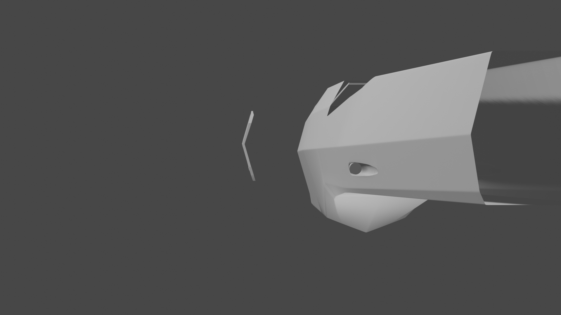
Madkoifish seems to have given the front of the nacelles some sort of interlocking plates, and this is my attempt to reproduce them.
They're pretty cool looking. I've labeled them radiator plates, if I had to guess their function, but they might also hold forward sensors, similar to the sensors in the nose of an aircraft, for all I know.
How do you all integrate the parts so smoothly? Any advice/techniques?
So far, I've had to use a combination of scaling and moving the vertices, sometimes vertex by vertex, so that they align/sit on top/the bottom of the component as a whole, and it's really slowing things down!
That wasn’t far from the Yamato’s nacelle supports from KLINGON ACADEMY
Ah, yes, the Yamato class (also know as the Yamamoto). That class actually has at least one variant, with the nacelles in SFC-II being mounted flat on the X-Axis/horizontally.
I'd actually like to make a Dominion War refit of her some day (it's not going to be happening any time soon)
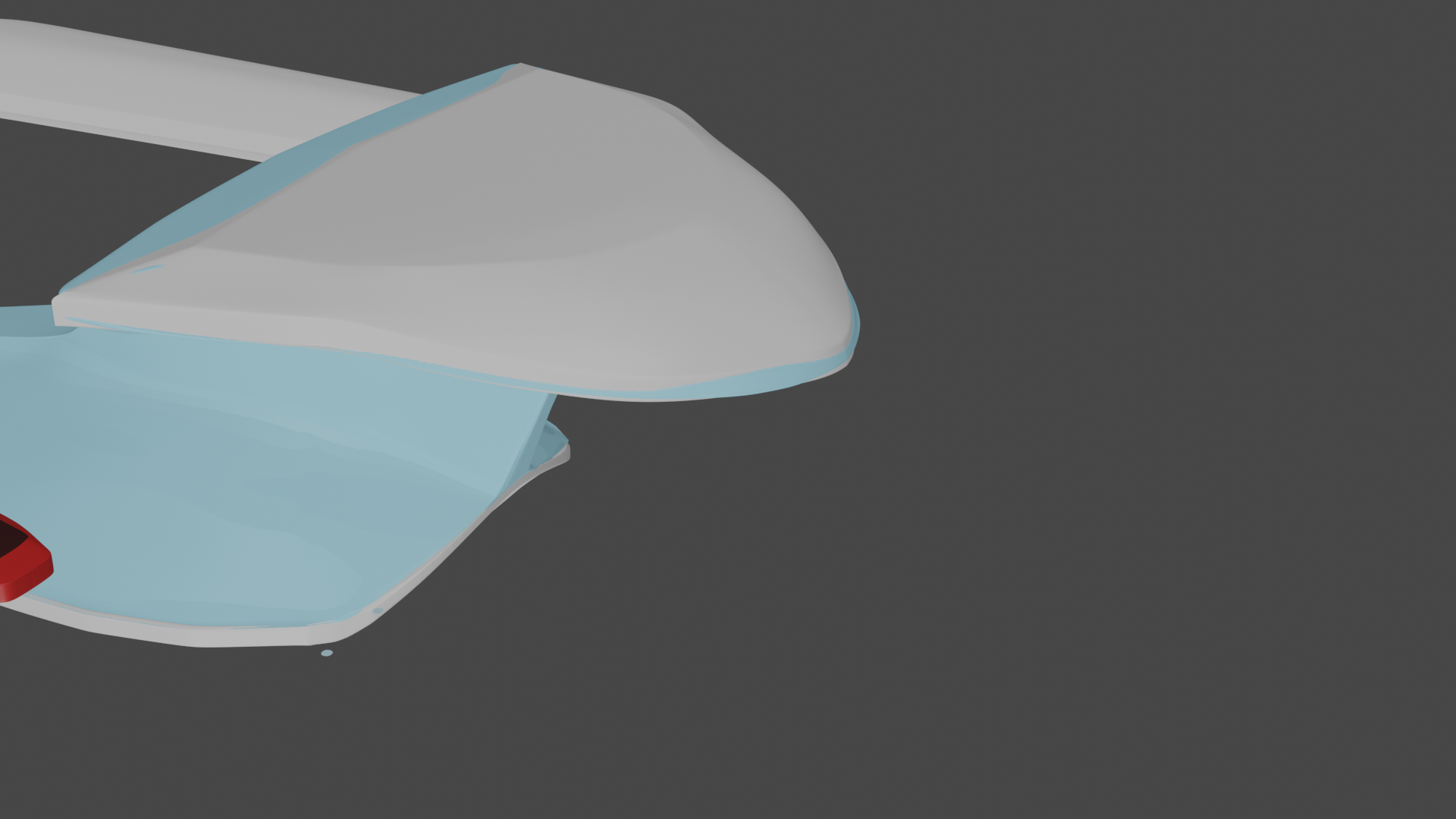
Most work has consisted of redoing and refining the engineering hull. The neck and bridge section of the engineering hull still requires more refinement, while I have decided to make the mid-section for the lateral sensors and engineering bridge separate objects, rather than layering on an ungodly amount of subdivisions to get the shape I need. But this has resulted in complications, such as making the engineering mid-section and the rest of the engineering hull appear as one object.
Finally, I worked on the basic shapes for the Nav Deflector. Fitting everything together has been the most challenging parts, whether it is blending different objects together, or attempting to make them appear as separate objects. I find that the magnet tool works sometimes, but other times, slowly nudging vertices gets the best results.
Getting the housing for the main deflector to look right has been, and continues to be a pain. It took two attempts to get it to look right, the second of which I did as a separate object. And then I got rid of most of the subdivisions because that will make it much easier to merge with the rest of the secondary hull as a single object! I probably should have done a render before I did that! Duh!!! But third times gotta be the charm!
It's not as though I haven't wanted to have a Sovereign class. Working on it is taking a lot more of what meager time I have if I had IRML or Pixelmagic's Sovereign, but then I'm giving my model something that for all of their detail and accuracy, lack. That, and I'm not certain I could get them to work in Blender, even if I could get my hands on either one! At this point, I've been using whatever images I could find of either two models to reference the details and exact hull form that orthos cannot provide.
I'm actually very surprised that I haven't seen anyone work on a Sovvie with the hull separation similar to the one depicted in the SOTL calendar. Looks like mine might be the first! Apparently, it also has shuttlebays built into the battle hull, making her a sort of battle carrier! That will be fun to model in (or frustrating and take too long!)
It took me three damn attempts to get it to look like this, often only having 2 or three hours at night to work on her.
I probably should have started on a damn Nova for practice first. Hell, I might still take a break from this eventually, and start on a Nova, resume work on the Paladin, or both!
After fighting with corrupt vertices that was stretching and warping parts of the shape after merging the deflector housing and the rest of the engineering hull into one shape (I'm starting to think it might be better just to use separate objects as templates using the magnet tool, rather than joining them, since it always seems to cause corrupt surfaces), I've found that the leading edge is no longer smooth (as visible in the first render), but has a sharp leading edge.
Has anyone else had this problem? I've tried altering the merging distance for the mirror tool, nudging vertices as close as possible to the middle down to the maximum magnification, and even tried redoing the geometry of the front prow. I still haven't been able to get that smooth edge back.
Does anyone know how to fix this (aside from just starting over the geometry, section by section, or just pretending it isn't there)?
If that doesn't do the trick, then not all of your verts are at zero. To make sure your verts are exactly at the zero point for the mirror modifier, it's better to hit "N" to bring up the properties and make sure any verts on the edge of where you're mirroring are exactly at zero. This involves selecting them one by one and making sure they're at zero. Alternately, you can select them all on that edge and hit "S" to shrink and the letter corresponding to the axis you're using (X, Y, or Z) and then shrink that axis to zero. Then, with them all in a nice neat line, you can use the object properties to make sure they're all at zero. (personally, I'd do this over individually selecting them, as it's less time consuming.
If you're using a mirror modifier activate the clipping mode. It'll stop any vertices from going over the mirror point, so all you have to do is move them to the middle and they should merge.
Make sure that the sub-d modifier is below the mirror modifier as that can also cause this issue.
If instead you are using the mirror tool, it's likely that the normals on one side have been flipped which will mess with the sub-d modifier . To fix this re-calculate the normals, either with shift-n or through the menus Mesh>Normals>Recalculate Outside (alt-n on Windows to go straight to the normals menu).
Other things you can try to remove overlapping vertices:
Hope you manage to fix the issue, as what you have so far is looking promising!
For some strange reason, resetting the merge distance to 0.1 meters is what did the trick. I only noticed after I redid the very tip, using the magnet tool to get the exact same geometry, only to have it revert to the same shape when I merged the two objects.
Thanks for the suggestions though!
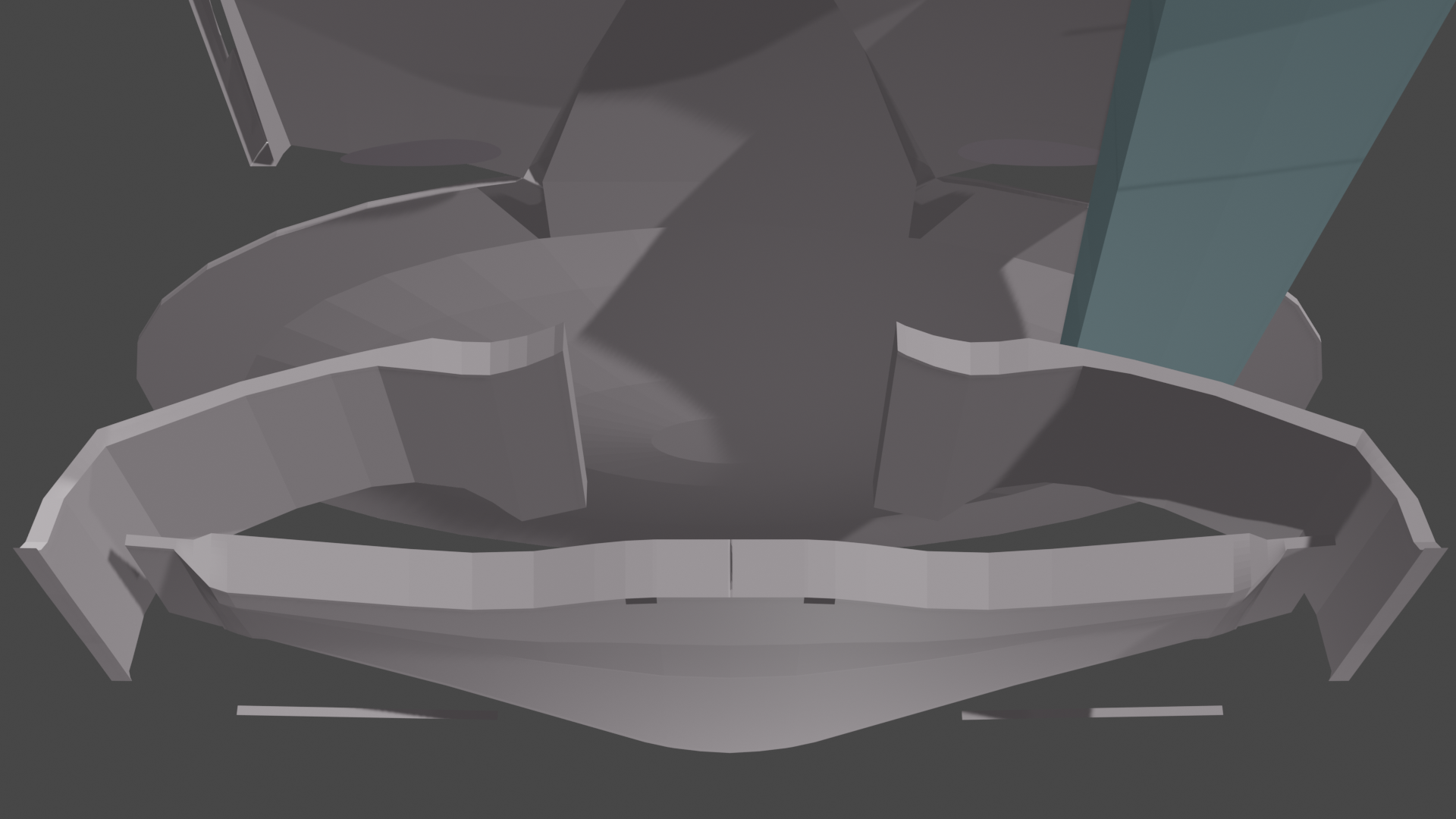
I've been hard at work on the Primary Hull, and it's finally beginning to take shape! This has been a huge challenge, due to all of the different angles and curves. I first started out with just using the spin tool to create the primary hull, but replaced that when it was just going to become too time consuming to slide all of the vertices to match the shape of the cutout in the side, as well as match the curve of the flat part of the saucer, AND the delta shape towards the rear. Interestingly, the flat part of the hull isn't quite flat, but has a subtle angle where the phaser array is mounted.
So on my second attempt, I instead started out with a cube, and when from there, carefully subdividing and moving vertices to match the shape. I also started out the raised area as a separate plane, before merging both objects into what you see here. I also had to make a practice run on the cutout, because it was hard to get just right. Still a lot of subdivisions that I need to add, but I want to first merge the upper and lower parts of the saucer into one object, that way, there are less vertices that I have to merge.
I've been using Michael Wiley's orthos as my reference, but they don't quite have that much resolution from the sides, so I've also been using images of the filming model, and whatever images of Nightfever and IMRL's model that I can get my hands on.
The Sovereign classes "steps" on the ventral hull are a delightful shape to model, but also challenging, and there are quite a few subdivisions that I need to add to perfect the shape, but first I need do the impulse assembly and then merge the two halves of the hull.